(Digital servo controller for DC motors with carbon brushes)

![]() Profi2S
CNC Servo Controller
Profi2S
CNC Servo Controller![]()
(Digital servo controller for DC motors with carbon brushes)

![]() Discontinued!
Discontinued!![]()
Only
product support !
![]() Please
see New
Profi2 Quantum Servo!
Please
see New
Profi2 Quantum Servo!![]()

(Profi2S Digital Servo Driver)
Modified: 2009. szeptember 01. kedd
Profi2S CNC Digital Servo Controller is capable to control DC servo motors with carbon brushes. It is suitable for both hobby-type and half-professional CNC applications. Its Step/Dir-system input and power supply demands fits to the Profi2 CNC Controller family (to the Profi2B base card) and often mixed-mode CNC drive (servo and stepping motor) can also be built (cost-effective mixed build-up). Because of its uniform, modul-type build-up controls for any number of axes and type can be bult. During its the most optimal fit to the popular Mach CNC control programmes was a key issue. Becasue of its high-power, double processor build-up it is suitable for wide range of servo-type or servo-like DC motors. It can be applied to both professional and home-built servo motors Based upon its two-level, sophisticated motor-protection system, it realizes a high-level motor-control well beyond the general hobby-demands
![]() Main
technical characteristics (DSP V1.3 + PID V1.3):
Main
technical characteristics (DSP V1.3 + PID V1.3):
- Step/Dir-system control inputs (Schmitt-trigger type TTL),
- arrange-able build-up, control for each axis, possibility of the application of mixed mode,
- control for DC motors with carbon brushes, with full PID algorithm,
- power transmission FET bridge for max. 90V, nominal 10A, and peak 14A DC,
- dynamics increasing (current-overshoot regulation),
- 10-bit PWM excitation control (20kHz),
- counter-current and passive (mixed mode by PID) motorbrake-handling,
- 2-channel (A, B), quadrature encoder handling,
- level-matching by TTL and OC encoder inputs (digital/analogue), with power supply,
- high-speed, double processor build-up (DSP + PID),
- upgrade-able firmwares (through ICP),
- stepping frequency of maximum 51 kHz,
- optimalize-able encoder handling with a division of 200 - 1000,
- signal and power supply compatibility with Profi2B,
- stress test (by the means of Test button),
- +- 65535 step virtual error buffer,
- real-time error-signal monitoring and recording (by using Profi2S Servo Monitor + monitor adapter, through RS232C connection),
- easy configuration (by jumpers and potentiometer trimmers (DSP + PID),
- complex error indication and status signals by LEDs,
- POST power-transmission tests and error indication,
- E-Stop input, with emergency stop (stop by motorbrake),
- 2-level, internal protection system,
- error signal output (collected TTL error signals toward the PC),
- protection against thermal overload (by a thermo sensor, heatsink temperature monitoring),
- protection against error buffer overrun,
- slip (tracking follow-up) error indication,
- motor peak-current limit (by potentiometer trimmer adjustment, and indication),
- protection against getting stuck of the motor,
- protection against encoder over-rotating,
- high speed impulse memory, optimalised to Mach3,
- high.level ,noise protection,
- installed cooling,
- 2-sided, partly SMD mounted PCB.
- etc...Documentation (Hungarian V1.3.0):
(Profi2S_Gepkonyv_ V130.pdf,1.6MB)
Attention! The most up-to-date information/changes can be read in the online manual (downwards).

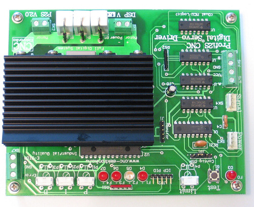
(PCB V2.0)
Profi2S CNC Servo Controller performs the servo control of DC motors
with carbon brushes by the means of a 2-channel incremental encoder. Because of the
encoder-feedback a closed-loop position regulation is realised.
Unlike stepping motor controls, here a regulation takes place, - therefore
in case of correct asdjustments - no steploss may occure. The control electronics uses
a lot more information, therefore a more intelligent drive-method can be realized.
The control (PID) forces the motor into the intended position (because of the encoder
the control always has exact information), and if it is not possible (e.g. because of getting stuck),
then this can be signalled to the PC, so the user can be notified about the error, and
he can prevent the error even during work.
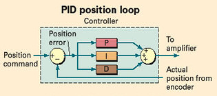
The adjustment of the more complex drive-method (PID)
is more complicated that that of the stepping motor controller. During adjustment of the PID
the tuning of the Controller to the unit of the given motor + mechanics takes place
(a little bit even to the settings of the CNC control programme).
In case of these controllers the adjustment of the PID is supported by additional electronics and
by special software, we can provide a portable, handheld, spectacular device.
This can be purchased as an option. This device is Profi2S Servo Monitor, which stores and presents
the transients of the servo controller like a digital storage oscilloscope.
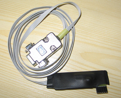
(Profi2S Servo Monitor adapter, RS232C)
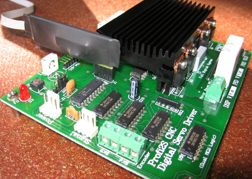
(connection to the pins of the monitor)
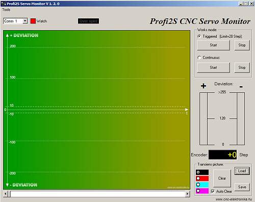
(Profi2S Servo Monitor software)
Information About the adjustment of PID regulation loop and about Motor Tuning can be found
The motors intended to use must meet the following requirements:
must operate with a DC voltage lower than 90V,
must be a type with carbon brushes,
the nominal current consumption must lower than 10A,
the motor must be a servo-characteristic type (all the types equipped with an encoder
meet this requirement),
In case of types without encoder the following should be checked:
Rotating their axis, it must rotate smoothly, without jerking. The types which jump into the
positions are not suitable.
The DC motor + encoder built-in units (e.g. manufactured servo motors):
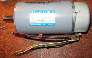 |
 |
| (complete servo motor with encoder) | |
Besides that DC motors + separately mounted encoders (might be mounted even at the end of the driven shaft):
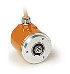
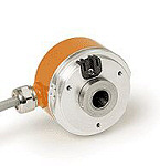
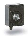
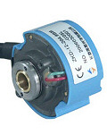
(encoders that can be mounted at the shaft-end posteriorly)
They must have 2 two-phase, so-called incremental-type channels (channel A and B).

(incremental channels with a phase-shift of 90 degrees)
Between the square-wave signals of the 2 channels, - which are generated continuously
during rotation of the axis, - there is a phase-shift of 90 degrees. From the relation of the 2 signals
the rotating direction can be determined, from the number of pulses, the extent of the swing
can be determined.
Many encoder have besides that plus channels (e.g. index), these are not used by the controller
(they do not have to be connected).
The electric signal levels of the channels must also be matched to
the inputs of the controller.
There are 2 types of the allowed signal levels:
1. TTL signal levels (with a signal level of +5V),
2. analogue, open collector trtansistor (OC*) outputs (the controller contains the internal 2k2 pull-up resistors and other signal forming parts).* OC= open collector (transistor output)
The connector of the encoder (SK5, SK6) containsteven the TTL
power supply, in case the voltage for the encoder is necessaryin (+5V, max. 100mA
current load).
The resolution of the preferred encoder should be between 200 .... 1000 Step/rev.
It is possible to modify the base resolution of the encoder in 2 stages (vide infra).
The resolution of the servo motor will be determined jointly by the resolution of the encoder
and DSP setting of the controller. This resolution can be further modified by other mechanical
gearing of the CNC machine and the programmable resolution (which is the smallest programmable
displacement) of the machine will be determined by all the above mentioned things.
Detailed information about this topic can be found at
About Motortuning.
Available servo motor:
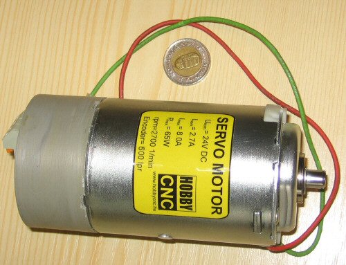
(DC 24V, 65W, 2700 rev/min, with an encoder of 500)
Integration into a system, PC connection:
Profi2S CNC Servo Controller is able to work with any component belonging to Profi2 family. The connection between the Controller and PC is realised by Profi2B base card.
Profi2B card provides the necessary Step/Dir signals for the Servo Controller, as well as the power supply for the digital parts. 4 pieces P2S Controller can be connected to a P2B card and a 4-axis CNC controller can be realised in this way. Using Mach3 control software and an additional LPT port it is possible to double the number of P2B cards. Detailed information on the card can be found at Description of Profi2B I/O card.
The mixed installation of single axis controllers (Profi2S Profi2A) ) is also possible.
As a CNC control software the Mach family is recommended, using at the maximum (45kHz) operating speed.
Protecting functions and their signals:

(LEDs)
Profi2S CNC Servo Controller has a 2-level complex protection system. The buil-up of some functions is optional, which is intended to raise the comfort of the controller, other functions protects automatically the Controller and the motor.
Protection levels:
1. Automatic protection. Whe it comes into action, the motor is stopped by motor-brake, the Controller is turned off and LED signalsd are produced This situation can be resumed only by restarting the Controller. Eaxh automatic protection generates an error signal on the error output, by which the CNC software running on the PC (e.g. Mach3) can also be stopped.
- POST* test:
During each switching-on the controller checks the FETs of power transmission bridge. If any of the FETs is found to be faulty, it lights the F1-F2-F3-F4 LEDs and prohibits the controller. This signal refers to short circuit first of all. In such cases service must be provided. When the motor power supply is present, the test is able to perform diagnostics, even when the motor is not present.*POST = Power On Self-Test
- Overrun protection of the Error register (2-level):
When the error signal continually exceeds the Step value of 255 for 3s, the Controller stops the motor by motor-brake and prohibits further operation.
It is first of all for protection against reverse connection of the encoderand protection against getting stuck of the motor. During its operation it gives a signal through the F3 LED.
The Error* register (DSP) is capable to store +- 65535 Step deviation, which does not cause blockage if it can be corrected in 3s. In case of DSP overrun, it is indicated by fast blinking the F0LED.* Error register = error-level register, which measures the deviation between the intended and the real mechanical positions in encoder Step. If there is no deviation, its value is 0.
- Motor over-current protection:
The Controller continually measures the current consumption of the motor and reaching the current value adjusted by the Limit potentiometer trimmer it limits the current. The fact of limiting is indicated by lighting the F4LED.- Motor overload protection:
If the over-current limiting of motor continually operates exceeding 10 s, the protection will stop the motor and prohibits its further operation (the F3LED continually lights).- Controller overload protection:
The temperature of the heatsink is continually measured by a thermo sensor and above about 85 centigrades it prohibits further operation of the Controller. The protection signals this condition by lighting the F1 LED.- Encoder overrotating protection:
Because of not proper configuration of DSP, there can be imagined suchan adjustment, at which the motor is able to rotate the encoder at a speed that is higher that the allowed speed too. In such cases this protection comes into action, which indicated the occurrence of the error by continually lighting the F0 LED and an error signal is also produced on the error output and Controller stops the motor by motor-brake. To clear this signal, the Test button must be pressed. To determine the treasure-value of this signal, Profi2S Servo Monitor programme contains a calculator aid (see the description of the programme).2. Protection through the PC. They do not stop the Controller, they only produce only an error signal on the Error output. If this output is connected to one of the Inputs of of Profi2B card through a 10V Zener diode and the controlling software is properly configured, then this signal is able to stop execution without pulse loss. In certain conditions the work can be continued without producing waste products after correcting the error.
- Slip error signal (follow-up monitoring):
If the value of the Error register continually exceeds 10 Step for at least 2s, an error signal is generated on the Error line. When this error persist, it is indicated by lighting F2 LED too. It indicates first of all wrong PID settings, and motor overload and qualifies the accuracy of the follow-up.
In case of properly set PID controller, the accuracy is within +-3 Step value. The actual value can be checked by the Profi2S Servo Monitor at any time.
(Error + GND + E-Stop connector)
The Controller has an emergency-stop function, which can be activated by a push-button located
between E-Stop and GND pins.
When this is activated, the Controller stops the motor by emergency brake and prohibits its further operation,
as well as an error signal is produced on the Error output. To resume this situation, the system must be
restarted.
It is important to know, that emergency-stop always operates immediately in any kind of conditions,
while the Stop comand issued on the PC might as well affect after several seconds because of
the pulse buffer of the Controller. The Controller got into oscillation because of wrong setting (PID)
can only be stopped by emergency-stop or by turning-off.
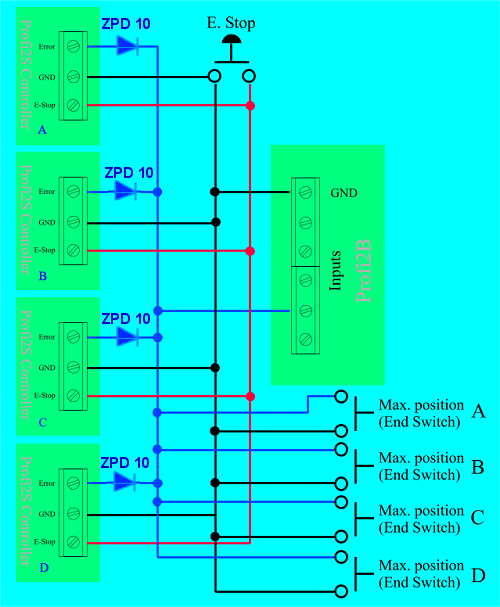
In full build-up, the protection must be wired in the following way:
(integrated protection + end-position inputs)
The above figure showsw a 4-axis Serevo Controller, which occupies
only 1 input on the Profi2B base card, yet both the Error signal and all the 4 pieces maximum end-position switch
will be processed. When they work Mach3 will be stopped by E-stop (in case of suitable configuration).
The circuit diagram contains the external E-stop push-button, which will stop Mach3 if it is properly configured
(the signal of E-Stop appears on the Error output of the Controller).
When the external E-Stop is operated, the stop without pulse-loss is not guaranteed
(the determination of 0 point will be necessary posteriorly).
The above presented figure does not show the end-position switches of the other end of the axes (or the Home
switches), they also must be taken care of (see at
Profi2B description)
The zener diodes ZPD10 match the TTL signal levels of P2S and the 15V levels of P2B.

Mechanical buil-up and installation:
Buiuld-up with one card for each axis, PCB sizes: 140×112 mms,
with 4 pieces of 3 mm bores. The distance of the boreholes is: 130×102mm.
It is preferable to make a block of a number of Profi2S cards according to the number of axes
(maximum 4 pieces of Profi2S cards can be connected to 1 Profi2B base card).
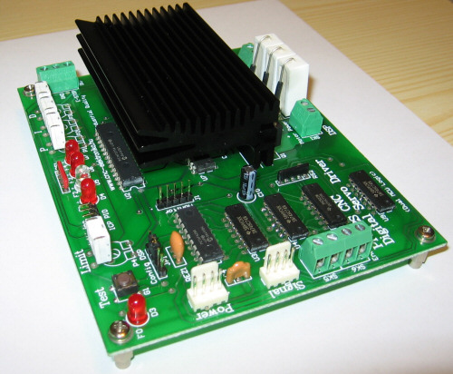
The Controller can be mounted by setting on the edge, and one can be mounted to the top of the other, so that the possible smallest place could be demanded. Care must be taken of the free ventillation. The optimal buil-up of the controller is a block, where the cards are mounted set on their shorter edge, one is mounted to the top of the other with spacers.

(Block-type build-up of P2S)
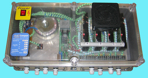
(Compact buil-up of Profi2)
It must be placed far from (electric) noise sources. By placing it into a box, it should be protected from mechanical effects, dust, but the free ventillation must be ensured. Do not expose it to shock.
In case of motors with nominal current consumption more than 4A forced cooling (by fans) is necessary.
All the wires should shielded mounted.
The high-current wires (connection of motor and its power supply) and the inputs of the encoder
are on a screwed terminal. The cross-section of the wires is maximum 1.5mm2.
All the high-current wires should be shielded twisted pairs. For this purpose the socalled industrial
4 - 20 mA signal cable, which is a 4-wire (2 twisted pairs) shielded with a cross section of 0.5 mm2, is very well suited
(available in special electric shops).
(2×2 twisted pairs, with a cross section of 0.5mm2)
The wiring of the Encoder must be done using shielded cables by all means.
Care must be taken of using the possible shortest wiring and placing the wires far from high-current
wires. The shielding must be connected to the GND terminal located on the Encoder input terminal of
the Controller. The shileding (and the GND terminal) must not be connected to the metall case of the CNC machine.
The metall case of the CNC machine must be connected to the protective ground of the current outlet.
If power supply must be provided for the Encoder, the the power supply voltage (if there isn't inside) must be filtered
by a capacitor of at least 10 uF next to the Encoder (the capacitor must be connected to Vcc and GND lines).
Care must be taken of the right connection of the motor power supply. In case of wrong (reverse) connection, the
Controller goes wrong.
The high-current witing must be placed as fas as possible from the Controller.

Designing the power supply of the motor:
The motor does not need a stabilised voltage, but a massive filtering using a capacitor of at least 1000 uF/A must be provided. Whe calculating the current demand, the nominal current of the motors should be taken into account (when one power supply is applied, the summarised value must be taken)!
When selecting the motor power supply voltage, the operating voltage of the servo motors
intended to apply must be taken, and the 1.2 - 2 fold of this value should be applied.
For example for a servo motor of 18V, 24V - 40V is suitable.
When mixed mode driving control is being built, (stepping motor + servo axes), a common power supply can also be used, if the power supply voltage is suitable for both type of motors.
Application of switching power supplies (like power supplies of PCs) is not recommended. (The elctronis of the switching power supply may be bothered by the PWM current regulation and they may down-regulate without any real reason), the classic type of power supplies (tranformer + rectifier + filtering by capacitors) are recommended instead.
The motor power supply is connected to the Controller through SK1 terminal. Take care of the right polarity. Shilded wires must be applied

(Connection of the motor power supply)
The outlet terminals of the DC motor must be connected to the SK2. Polarity does need to be taken care of, the rotating direction can be chaged within the CNC control programme.

(Connector of the motor)
When selecton the cross section of the wiring, the nominal current of the motor must be taken into account. Shielded wires must be used.
Digital Power and Signal connection:
The digital power supply and signal connections are lines of pins. The pin-line connections are ed using standard internal PC (CD-ROM - motherboard), audio (shielded) cables. The usage of sush (shielded) cables, with wide black connector at both ends is strongly recommended. The connectors are positioned, reverse connection is not possible.
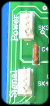
(Power and signal connections)

(shielded signal cable)
Care must be taken not to exchange the signal and power line. Wrong connection may cause the Controller to go wrong immediately.
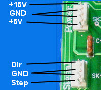
(internal allocation)
| Power supply: | Current consumption (maximum): |
| +15V* | 25mA |
| +5V (+-10%) | 35mA + Encoder (usually: 35mA) |
Signal levels of the signal connector: TTL.
+15V* = Allowed range of igniting voltage of Fets: 11V-18V!
Exchanging the 2 wires may lead to damages.
The wires should not touch the heat sink (danger of melting).
Letter, A - D must be attached to the 4 pieces of Profi2S Controllers,
and the letter attached to the controller should be written onto it by an
alcoholic makrker. Later, based upon this marking the bit allocation table - controller
assgination can be performed.
The signal connector of Profi2S must be connected to the signal connector of
Profi2B
(upon the denomination)!
The power connector of Profi2S must be connected to the power connector of
Profi2B.
Regarding the power supply connections, the marking has no special importance (they are the same).
ing the power supply system, it is possible to apply a common
motor power supply (all the motors have the same power supply), or distributed (even separate supply for each axis)
power supply system can be ed (in the later case only the minus terminals of the motors must be common).
The digital GND (Profi2B) and the minus terminals of the motor power supply must not be combined
outside the Controller (they must be combined inside the Profi2S Servo Controller).
Connection and testing of the Encoder:
The connection of the Encoder is realised through the SK5 + SK6 terminals. On the terminal the connections of Vcc and GND also can be found (if they were needed by the encoder).
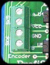
(Encoder connector)
The encoder must be connected with shielded wiring by all means.
Care must be taken of the polarity of the encoder power supply, in case of revewrse connection it may go wrong.
Exchanging the channel A and B of the Encoder does not cause any failure, but it leads to
abnormal operation of the Controller. Whe they are exchanged, the Controller will start the motor
at maximum speed toward one direction, because the feed-back will operate reversely.
Therefore the motzos must be connected to the mechanical parts
during the first tests.
If this might happen, the Controller would stop motor in 3 s and would prohibit its further operation.
Checking the connections:
Turn the Limit potentiometer trimmer of the completely wired Controller into approximately 1/3 position (0 position is clockwise direction), and turn the other potentiometer trimmers to 0.
(Position of P potentiometer trimmer)
(Position of Limit potentiometer trimmer)
Turn on P2B and the motor power supply.
gently move the motor-shaft by hand.If the motor suddenly starts (at a great speed), the the connection is reverse.
Turn off the Controller.If the motor dos not spin, then the connection is correct.
In case of reverse connection either the line A and B should be exchanged, or the excitation lines of the motor (SK2) should be exchanged.
Ajusting the Encoder handling (resolution):
The DSP processor of the Controller can handle the Encoder in 2 ways:

(place of DSP jumper)
| Its function: | Jumper position |
| Encoder doubling: | - |
| Encoder 1:1 | 2-3 |
(Adjustment of the DSP Config)
The pin 1 on the DSP Config pin-line is marked by a small white point.
The adjustment of DSP is indicated by the speed of blinking of LED F0D too,
(at 1:1 is gets slower, at doubling it gets faster). To validate the adjustments the Controller
must be restarted, or the Test button must be pressed (this is accompanied by move of the motor).
Further information can also be found at the description of
Motor Tuning.

(F0 LED)

The setting-up of the software is basically the same as that of written about Profi2B base card Detailed setting-up information can be found here , please read it carefully.
(the software must be set-up
onto Profi2B card)
Only the deviations from the base settings are discussed here. In the description of Profi2B Setup (Hungarian languange) a fast setup file can also be found, so that the system could be put into operation easier.
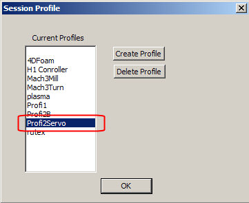
(the installed fast setup creates a new Servo profile)
Because of the higher speed necessary for the servo drive, it is recommended to make Mach3 work at a speed of 45kHz.
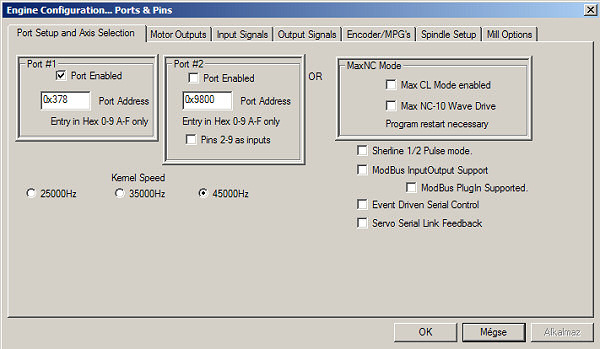
(the use of Kerner speed of 45kHz is recommended)
The following adjustment has a great importance:
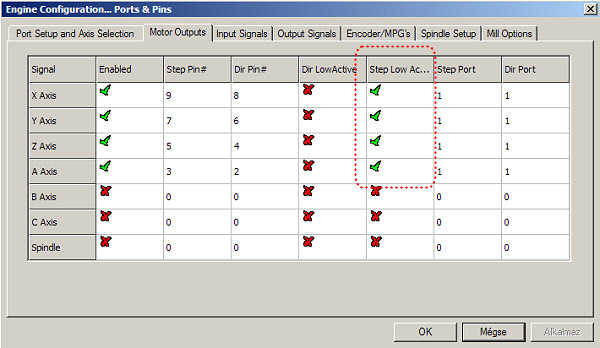
(Adjustments necessary for Profi2S Controller)
It is important that the Step Low Active signal should be set at P2S Controller. If both Profi2A stepping motor Controller and P2S Serevo Controller are used (mixed use), then the Step signals of Profi2A MUST NOT BE SET to Step Low Activre, but the Step signals of Profi2S Servo Controller must be set to LOw Active.
The full movement control of the motor is performed by the PID regulator, with the help of complicated mathematic procedures. The regulation works wth 3 parameters adjustable by the user. The 3 parameters are marked as P, I ,D parameters, a separate potentiometer trimmer belongs to each of them.

(PID potentimeter trimmers)
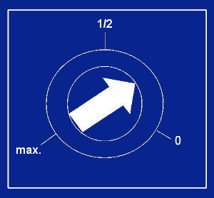
(P, I, D potentimeter trimmers)
The amplification of these regulation parameters can be adjusted by these potentiometer trimmers.
This process is rather complicated, see all the detalied information in the description of
Motor Tuning.
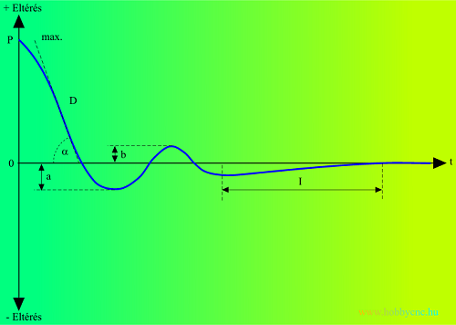
(adjustment of PID regulation)
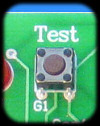
It has 2 functions:
1 - Validation the DSP Config (resolution of Encoder) and clearing the error signals of F0 LED. To perform that, it has to be pressed only once.
2 - The Test button can make a stress situation for the DSP. By pushing it, an Error level of +255 vill be created suddenly, which the PID tries to handle as soon as possible. It can be used to test without external Step signal, and first of all to check the stability of the PID adjustment. The tests should be performed using Profi2S Servo Monitor in triggered mode. Details can be found in the description of Motor Tuningn.
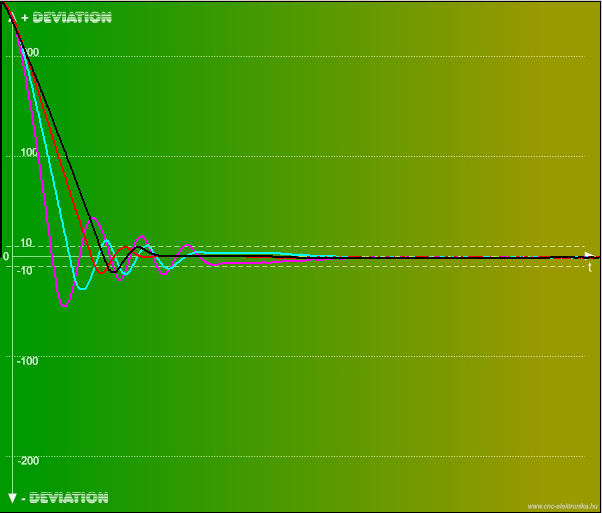
(transient test of the Test button using Servo Monitor)