(Adjustment and fine tuning of PID parameters)
![]() Profi2S Motor Tuning
Profi2S Motor Tuning![]()
(Adjustment and fine tuning of PID parameters)

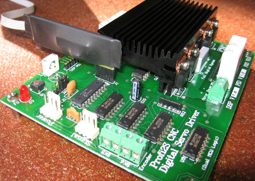
(Profi2S)
Modified on 2007. október 10. szerda
| Content: |
| Theory |
| Tuning of PID |
The operation of servo controllers totally differs from that of stepping motor controls, therefore it is necessary to apply a special motor- tuning procedure. The principles of the control and the processes taking place are complicated, that's why they will here only briefly discussed (on user level).
Fitting of Encoder:
DC motors do not have a predetermined stepping position as stepping motors,
this function is realised cmpletely by the control with the help of an encoder
mounted on the motor. This means a dynamic and continual holding in position
(in case of moving out of the position it will stand back).
The resolution of the motor is determined basically by the resolution of the encoder.
This can be modified in some extent either upward or downward by the control.
Profi2S Servo Controller can handle the base-resolution of the encoder in two ways:
1. doubling (multiplies by 2) 2. 1:1 (unchanged)
In case of applying Mach CNC softwares it is especially necessary, because the servo motor intended to apply (its encoder) can be optimalised to the stepping frequency of the software, which can be maximum 45 kHz. The maximum revolution that can be achieved can be calculated by the following formula:
fmax.=45000/Eresolution×60 [rev./min.]
fmac.=the maximum revolution available [1/min],
45000 = the maximum stepping frequency of Mach3 [Hz],
Eresolution= the jumpered encoder resolution,
×60 = changing the unit to minute
An example:
The maximum available revolution (in 45 kHz mode) using DC motor with an encoder
with base resolution of 500, with doubling encoder handling and using Mach 3
software controller is:
45000/1000×60=2700 1/min.
If the calculated revolution or the resolution is not suitable, it is possible to change the resolution of the encoder by configuring the DSP. In case of the maximum available resolution values the bandwidth of the controller must also be taken into account, therefore it worth using the Revolition Calculator of Profi2S Servo Monitor to perform the calculations.
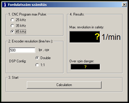
(Calculator of Profi2S Servo Monitor)
Important:
As the feedback of the whole system is realised through the encoder,
its resolution affects all the other dynamic features (lag, tendency to swing,
etc.). Try to apply the possible highest resolution so that the possible finest
and most precise driving quality can be achieved.
Taking into account the possible adjustmets the encoder resolution ranging from 200 up to 1000 are the most suitable for Profi2S Servo Controller.

Position-true follow-ip, swings, PID:
As the controller does not know in advance where to go in the step/dir systems,
it will follow the issued movement instructions with a certain time-delay. In case of
smooth movements this is extremely small and as a consequence it is negligable.
In case of sudden and rough change in the speed (e.g. in case of direction change)
this is a lot greater. The delay comes from mechanical inertia (momentum) and the
reaction-time of the motor + electronic system.

(sketched moving field)
The figure presented above shows a roughly sketched field deviation. The dashed red line presents the intented moving curve (with direction changes without speeding-up and slowing down), the blue line shows the real mechanical way. It can be seen that in case of speed-changes the regulation can follow the field only with certain swings and deviations. To solve this problem the so-called PID control procedure has been developed, which is applied by the controller.
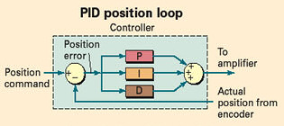
PID:
The PID control tries to hold the mechanics on the intended field. This is realised
by a motor excitation calculated from the resultant of three main component. The PID
shortening comes from the initials of the three components.
P = Proportional (proportional component);
I = Integral (slower, error-summing-up component);
D = Derival (faster, reacting to the faster speed-changes).
P = proportional component:
It raises the excitation of the motor proportional to difference between the real
and intended position.Its extent affects the motor dynamics (with how much force should
the motor react to the increasing errors).
I = Error summing-up. If small errors remain in the position, then summing -up them after a while, it amplifies them and takes the motor to the correct (intended) position. Its task is to eliminate the small errors. Its reaction is relatively slow.
D = fast-reacting component. Its task is the reaction to the fast, sudden changes with an excitation of extra dynamics. It raises or reduces the excitation proportional to the speed of the changes, gearing up by this the reaction or swing-dumping (negative reaction) of the motor. It is responsible first of all for swing-dumping (stability) of the system. It works only when speed-changes take place and it is proportional to the speed of the changes.
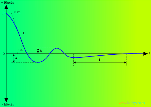
(PID regulation, transient curve)
The curve above shows a reply to a field demanding a fast (leap) position change (mechanical setting in). The above mentioned condition shows a motor approaching at a high speed hurtling down its 0 point, then the mechanics comes to a halt with swings and its sets in to 0. The interventions of the PID control can be well observed.
P gives the base excitation, which increases proportional to the extent of the deviation (gives the base torque to the motor). D gives the maximum angle of incidence (its damping), which is responsible for damping of swings. The greater the angle is, (the smaller the effect of component D is), the more and greater overshoot (a + b) can be measured, and the more time is necessary for the system to steady down. Component I is responsible for correction of the remaining position errors (amplifying them so much as the time goes, that it forces the motor to the intended position). It has a great importance in realisaing of the field-true movement.
The effect of PID components:
- component P: By raising it, the movement of the motor is more field-true, and the torque of the motor increases.
- Low P component: great position errors (deviations from the true position) ,slow reaction, weak motor.
- High P component: overreacting, swinging system (oscillation), jerking motor, tendency to swing after direction changes.- By raising component I the position follow-up will be more tigthen, it keeps harder the 0 error-level. In case of follow-up error, the system tries to set in position faster and harder.
- Low I component: the remaining error will not be eliminated (not position true field follow-up appearance and subsistence of remaining errors after direction changes).
- High I component: swinging, oscillating mechanics (overcompensation), heavily jerking, swinging motor. Endless, more and more stonger oscillation.- By raising component D, the accelerations will be more dynamic, the slow-down will take place with higher damping. The stability of the system increases (damping of swings), but the reaction time will also increase.
- Low D component: oscillating (swinging) system, swings that can be damped only slowly or not at all after direction cganges.
- High D component: over restrained (overdamped) rigid motor-drive (strong upwarming of the motor and sluggish reaction, grouchy voices from the motor).
In the course of adjustment of the motor, all the three components must be simultaneously adjusted, the perfection of the control will be simultaneously determined by the three components, therefore it is possible to find a good control at more points.

(PID)
As the phenomena cannot be followed-up by nacked eye, Profi2S Monitor
must be used for precise tuning of the control. Details about that can be found at
Servo Monitor.
![]() To know its content is necessary by all means, therefore read it carefully before you begin the work!!!
To know its content is necessary by all means, therefore read it carefully before you begin the work!!!
(measurement and analysis)
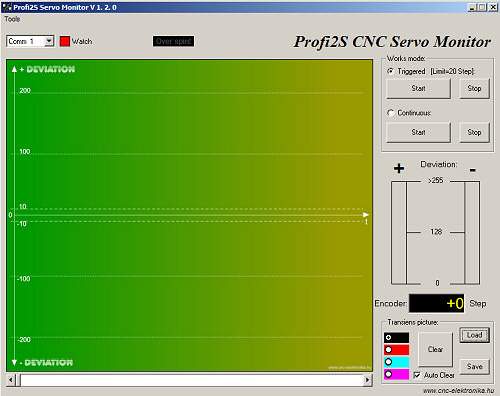
(Profi2S Servo Monitor)
The PID control must always be adjusted together with the mechanical parts (with its mass and inertia), and using possibly the CNC control software you want to apply (e.g. Mach3) (using the speed and acceleration set-up in that programme). Running the monitor and Mach3 at the same time, the adjustments must be performed at axis after axis.
The knowlidge of the use of Mach3 CNC control programme is necessary for the tuning. Information can be found at the description of Mach3.
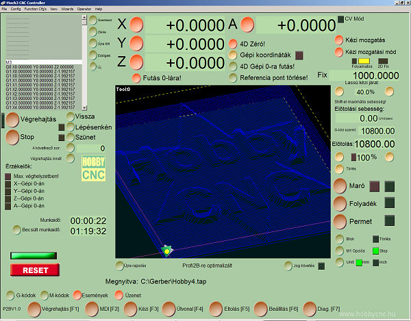
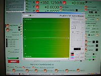
(Profi2B Hungarian screen with Mach3)
Before tuning Mach3 must be configured to the Profi2B card, and the base resolution and speed/acceleration values of the CNC machine must be set in.
During tuning the mechanical parts will move back and forth,
and the tuning will be preformed by measuring (with the help of the Monitor) these movements.
The aim is that the mechanical parts will be able to follow-up the moving field wished by the
PC with the least possible error.
The moving field will be determined by a simple programme written in G code, this programme
must be loaded into Mach3, and it must run with different speed and acceleration values.
Movement generating small programme (G code):
(File Szogteszt.tap )
(Wednesday, 14, April, 2004)
G90G80G49
F2000
G1 X0.0000 Y0.0000 Z0.0000 A0.0000
M98 P1234 L50
G1 X0.0000 Y0.0000 Z0.0000 A0.0000
M5M30
O1234
G1 X0.0000 Y0.0000 Z0.0000 A0.0000
G1 X700.0000 Y00.0000 Z0.0000 A0.0000
M99
The wished axis (here axis X) will be moved at a speed determined (here 2000 mm/minute) in F line of the programme (here F2000) between 50×, 0 and 700 mm, back and forth (by performing cyclic subroutine calls). The highlited lines must be edited from time to time during the test. Line F must be chaged here F2000) if you would like to increase the speed (mm/minute), line G1 X700.0000 ... must be chaged if an other axis is intended to be moved (e.g. for axis Z it must be: G1 X00.0000 Y00.0000 Z700.0000 A0.0000 ). If the value of move (here 700mm) is not suitable, it can be overwritten by any number ( in mm).
Profi2B screen of Mach3 offers a possibility to edit the code (through the Notepad of Windows).
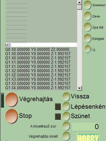
( Edit button of Mach 3 is to modify code G)
Procedure of tuning (for each controller):
Important!
Before performing any test, make sure of the correct connection of the encoder.
In case of reverse connection (channel A and B) the machine will run toward one direction
at full speed. You can check whether the connection correct, if you decouple the motor from
the machine and switch the motor on and try to move its axis. It should not run away to any
direction. In case of reverse connection exchange the two ends of the motor.
1. The intended encoder handling must be jumpered on the DSP Configuration (see above). This also determines the extent of the available resolution, which must be set in in the Mach3 referring to the intended axis. In case of replacing the jumper, the controller must be restarted or the Test button must be pressed.
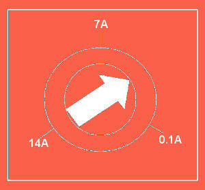
2. The current-limit for the maximum allowed motor peak-current must be adjusted (by Limit potentiometer trimmer P4). By turning the potentiometer trimmer to clockwise the current limit will be reduced (its about 0.1 A in the end position), by turning it to counter clockwise the current limit will be raised (about 14 A in the end position). The peak-current consumption of our motor must be estimated and the potentiometer trimmer must be adjusted to this position.
(Limit)
(peak-current limiting, Limit potentiometer trimmer)3. For the time of the tuning do not connect the protection line (Error line) to the Profi2B card (so that it could not generate unnecessary stops for the time being).
4. The resolution, speed (for the time being let it be min. 1500 mm/minute) and the acceleration (for the time being let it be 100 mm/s2) of the axes must be set in the Mach3. The acceleration and perhaps the maximum speed may be necessary to be changed during the test.
5. The code G must be loaded into Mach3 and the move for the axis wished to be tested must be set in by editing the code ( if e.g. axis Y is going to be tested, then Y coordinate must point to 700.0000, the others must be set to 00.0000).
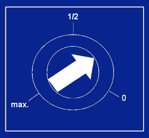
6. The 3 PID potentiometer trimmers should be adjusted to minimum (0 is in clockwise direction). then potentiometer trimmers P and D must be raised to about 1/3 position.
(Adjusting potentiometer trimmers P and D)7. All the axes of the machine must be adjusted into middle position and make sure whether the distance to both ends is gretaer than 700 mms (if not, then the extent of the move in the test code G must be reduced).
8. Start the programmes and the test. Observe the movement and if the system should began to swing heavily, reduce component P.
9. In continuous mode measure the lags by using the Monitor programme (using bar graphs) and by adjusting component P set in a delay between 10 and 20 Step (measuring in the smooth section)!
(Continual mode)10. If the system swings heavily after direction changes, then raise component D until the process becomes handleable (too high component D is not ideal).
11. By gentle raising of component I (turning into counterclockwise direction) adjust the system so that in case of smooth movements the controller could produce about 0 error (with weak swings around 0). Be careful, because too big component I can produce wild swings. Should this happen, turn off the motor and take back component I, then continue tuning.
(Potentiometer trimmer of component I)12. In case of this Mach adjustment a well-tuned controller can work on each point (even during direction changes) with 0 error (+-1 Step). The tuning should be continued (with the adjustment of components P-I-D) until this state is reached. If any mechanical part pulsates, seizes (up), then a bit bigger error can be accepted.
13. Check the system for errors at other speed values too (e.g at 10, 100, 500, 1000, 3000, 4000 mm/minute, etc.). When raising the speed a error increasing a little may appear suddenly at the moment of direction change, but it must be eliminated quickly by the Controller (by raising of component P or perhaps component I it also can be corrected, in case of gradually increasing swings component D can also be raised (but in this case the system must be checked again, -even at lower speed values).
14. None of the three components must be too high. When raising potentiometer trimmers you must stop at the position where the error diappears. Ignoring this rule will result in overreacting control.
15. If everything is all right the motor-acceleration value of a Mach3 can be raised and the error-peaks appearing during direction changes must be checked.
16. The best acceleration setting is that where the Controller is even able to hold the error level around 0 (max. +-3 Step) even during breaking and acceleration. If this value has been found, it means that our system is featured with this value. In fast mode short (impulse-like) error-singal is allowed even with a value of 50 Step. If this can be eliminated by the component I in the linear section, the acceleration that belongs to that state can also be applied (only in fast mode). The error level usually can be adjusted to a level of +- 1 Step value.
Continual measurement video (wmv, 9 MB)17. Stress test:
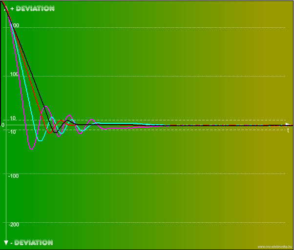
To perform this test, Mach3 must be stopped and by pushing the Test button of the Controller, the transient curve can be drawn up in triggered mode of Monitor. This curve is good if the system stands to 0 error with the possible lowest overshoot and swings. In this case the system must be capable to handle even a base signal jump of 255 Steps.
(transient curve)If the swings do not tend to disappear, then the present adjustment is not suitable. This case is usually featured with too high component I, or too small component D.
This test must be repeated several times.
(The effect of change of component D to the transient curve)As much component D is reduced, so much the angle of incidence increases (alpha), and so much the extent and number of overshoots increases (D<D<D<D). In case of too high component D the damping of the motor will increase very much and the motor will heat-up in greater extent.
By dragging the scroll bar the curve can be zoomed and its details can be studied.18. Position-holding test:
With stopped Mach 3 and in continuous mode an error signal of 0 (+-1) must be observed. Then drag the shaft of the motor with your hand and try to move it out of its position. The motor must force the shaft (with the force of its torque) to the 0 position. This also can be seen on the diagrams of the Monitor.19. If satisfactory results have been obtained in all the tests, then the adjustment is succesful.
Further tips:
If in code G higher speed has been adjusted than the axis speed set in Mach3, then the programme will hold in the motor (in this case the maximum speed of the axis must be increased in Mach3 motor tuning)!
If the LED F0 is continually lighting, then the motor is driven at too high speed. In this case the encoder handling must be set to doubling mode, or the speed must be reduced (Fxxxx). After that a given maximum (without Danger of overspinning Encoder) speed must be adjusted as the axis-speed of Mach3 (so that the system could not raise the revolution of the motor above this speed value)! The signal can be cancelled by pushing the Test button (by pressing it once) even during running.
![]()
(The green signal must also remmain during tuning.)
When the motor comes into swing, it cannot be stopped by the end-position
switch, because this switch operates through the PC.
By building in the E-Stop the Controller can be stopped in all conditions.
When the Controller was stopped by E-Stop, it must be restarted by all means.
The Step impulses of CNC softwares of poorer quality (e.g. KCam4) are not uniform enough. These may produce swings in servo movements. Their application is not recommended.
The trigered mode can also be used under running the test code G
(or even during working with the machine). In this case the recording will only start if
the error signal exceeds (at least for a moment) +-20 Step level! The handling of swings
appearing during direction changes can be studied by its use.
The screen of the curve can be saved into a file with extension of .bmp and after loading back
it can be used as a standard curve (a curve for comparison), (it remains continually on the
screen).
If the swings appearing during direction changes can no longer be reduced, then smaller accelerations must be applied in the adjustments of Mach3 Motor tuning.
Protectiv actions during the test:
The detailed description of the protection can be found at Description of the Controller.
(LEDs)
If F4 (overcurrent) LED lights up during direction changes, then the extent of acceleration lags behind from the result intended and the error will increase at this point (the excitation will be limited because of protection of the motor). In case of operation of the overcurrent protection the dynamics of the motor will not increase further. If the protection operates continually for 10 s (e.g. the motor seizes-up), then the protection will prohibit the Controller (the motor will be switched off and F4 LED will light-up and will remain lighting). In this state the Controller must be restarted by all means.
If the error signal is above 10 Step for more than 2s, then the Controller can stop the PC (the programme) by the means of Error line (the error can be corrected without impulse loss and in case of certain conditions the operation can go on further). This is indicated by F2 (Slip) LED too. Its build-up is not mandatory. If the error signal goes under 10 Step, then the signal will be cancelled. In the course of tuning this protection must be disconnected (or not built-in) so that it could not produce unnecessary stops.
In case of too high speed the motor is not capable to rotate so quickly as it is required by the PC, and the error sinal will be very high (more than 255 Step deviation can be measured on the Monitor). if this condition remains longer than 3s, the Controller will stop the motor by motor-brake and will prohibit its further operation (this is indicated by F3 LED)! Further operation can be done only after restart. If the encoder is reversely connected, this protection will stop the motor.
Should the Controller overheat, it will prohibit the motor and will switch it off, (indicated by F1 LED). Further operation can be done only after restarting it (and after it has cooled down).
If F0 LED begins to blink quickly, then Error register has overflown. Probably the motor is weak, or its voltage is low, or the overcurrent protection is too tight and it is not able to follow the movedment commands of PC.
If F0 LED is continually lighting, then the speed is too high for the encoder, and this may result in impulse losses. Reduce the speed.
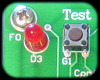
(F0 LED and its cancelling button)