(Its usage and download)
![]() Profi2S CNC Servo Monitor
Profi2S CNC Servo Monitor![]()
(Its usage and download)
(Finetuning of Servo)
Modified: 2007. november 25. vasárnap
![]() V1.3.2
V1.3.2![]()

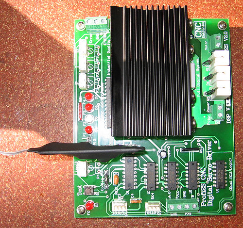
Servo Monitor presents and shows the mechnaical deviations of Profi2S CNC Servo Controller, i.e. the relation of the aimed (by the computer suggested), and the actual (realised by the motor) positions. With the help of the Monitor the Controller can be tuned together with the the motor and mechanical parts most optimal. The software communicates with the CNC Servo Controller through the attached adapter card.
(Profi2S Servo Monitor)
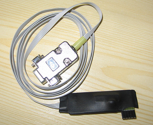
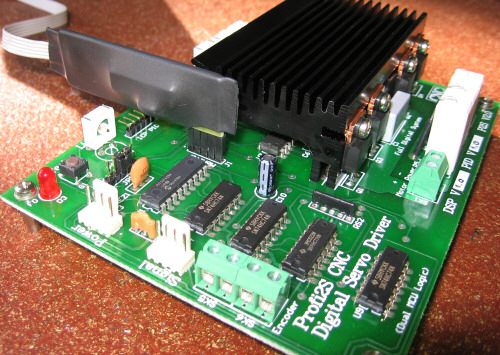
The Profi2S Monitor card has its own microcontroller and RS232C
interface circuitry. The adapter card buffers, makes the internal communication of the Servo Controller slower
and translates it to the standard RS232C language of the PC. Beside that it produces data-trigger
for the oscilloscope programme too (data-recoding synchronised to predefined events).
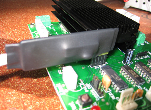
The card fits to the connector of Profi2S Controller Monitor (the pin No 1 of the card is marked with a white point), the other end of the ribbon cable connects to the RS 232C serial port of the PC
(e.g. Comm1). In case there is no (free) RS232C port, it can work by using a serial-USB converter through an USB port.
When the monitorcard is properly connected, the ribbon cable looks onto the potentiometer trimmers of
Profi2S.
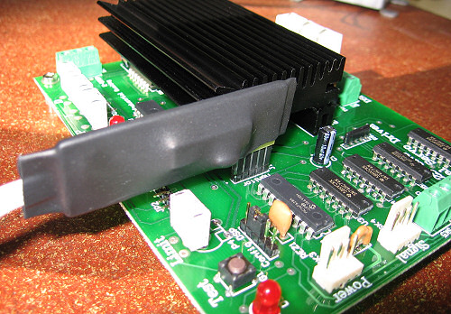
(connected Profi2S Monitor)
The Monitor software and the Mach3 programme controlling the CNC
can be run on the same PC at the same time, and the states of Servo Controller can be studied in real time.
The states become visible right after the fine tuning, and the most optimal PID settings
can be easily found by that.
The connection of the Monitor Card is suggested only when the Servo Controller is switched off, otherwise
short-time interferences may form in the internal communication of the card at the moment of the connection,
which may lead to faulty motor reactions or communication failures.
(Click to zoom.)
System requirements:
Because the high-speed data-processing a PC equipped minimum with a processor of 2 GHz, running
Microsoft Windows XP is necessary. If the CNC controller programme (e. g. Mach3) and the Monitor programme run on separate PCs,
then the PC running the monitor programme should be equipped minimum with a processor of 1 GHz.
![]() Usage of Profi2S
Servo Monitor
Usage of Profi2S
Servo Monitor![]()
(online manual)
(stress-curve)
After installation of the programme the communication port where the ribbon cable is connected must be assigned.

(marking of the communication port and condition)
When USB converter is applied the (serrial) number of the virtual serial port must be assigned.

(Connection through an USB port)
The color of the LED before Monitoring gives information about the state of monitoring (red = being switched off, green = being switched on).
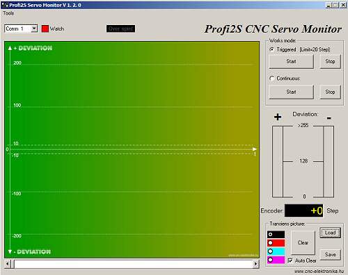
The software of the Monitor can run in two main modes:
1, Triggered mode. This is a digital oscilloscope mode, in that the software as a recorder stores for 2 seconds the mechanical deviations from the occurrence of a certain (pre)defined event, and displays it on the DEVIATION screen.
2, Continuous, fast display. It displays the Servo states in two bar charts and numerically under them at a great speed. This is a more simple and therefore high-speed display mode, which can run time-independently with no time limits.
The control buttons of the modes:
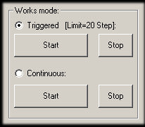
(using the modes)
1. Triggered mode:
Recording for 2s (storage of 4000 measurement results). The treshold of the trigger is 20 Encoder Step difference (deviation). Reaching this value
the recording is started. Recording can be started either plus, or minus direction.
After recording the results will be displayed on the DEVIATION screen in compressed format
(the whole record will be fitted to the screen).
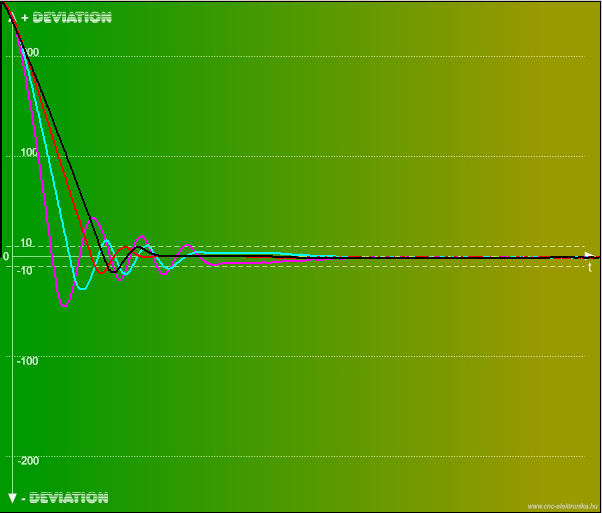
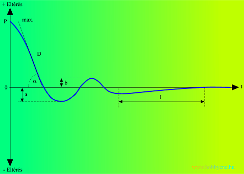
With the help of the scales on the DEVIATION screen the extent of the errors and the signal form can be studied (PID regulation).
(DEVIATION screen)
For the detailed study the lower scrolling bar should be dragged, then
the screen changes into 1:1 time-base and the detailed study of the curve can be done
(zooming).
The curve shows the mechanical deviation between the intended and realised state in the function of time.
This deviation is 0 (zero) in an ideal case.
It is first of all for studying the response to the unit jump (Test button on the Controller),
but the falloff in time of the deviations occurring during direction-changes can also be observed by that too.
(The curve of the mechanical setting in with changing cpmponent D as a response to the Test button)
About the interpretation of the curves and adjustment of the PID controller detailed information can be found under the Motortuning point.
(interpretation of transient curve is under
Motortuning)
The menugroup for the manipulation of transient screen (DEVIATION) belongs to that mode too:

(manimulation of graphics)
By the color-switch the color of the curve can be set, so the curves can be drawn to the same screen and
the effects of the different adjustments can be studied.
By the Clear button the screen can be cleared.
When the Aut. Clear is switched on
the screen will be automatically cleared before recording each record.
By the Loading and
Saving buttons the screen can be loaded and saved in .bmp (Bitmap) format. By loading a previously saved screen, it can be taken under the new curves,
and it cannot be deleted (e.g. etalon curves for comparison).
2. Continuous mode:
It is a simplified mode, but the states can be traced by continuous presentation.

(continuous monitoring)
There is no time-limit, it can run as long as you want. It has a great importance during the tuning of the PID controller. Details can be found under the Motortuning point.
(the fall-off the fast direction-changings [made to be slower])
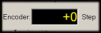
All deviations are in the term of Encoder Step (not in the term of PC step)!
In this mode the signals of the protection against Encoder overspinning can also be continually checked:
![]()
(Encoder protection monitoring in continuous mode)
A "The green color of the
Danger of overspinning " notice indicated the normal operating condition.
In case of too high Encoder frequency (revolution) this will change to red.
In such a case the revolution number of the motor must be reduced (within the CNC control programme).
This signal is also matched with the signal of F0 LED, which is placed on the Controller.
To cancel this signal the Start button must be pressed.
Work-aid menu:
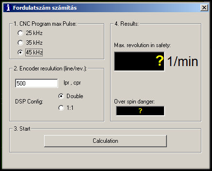
Revolution number submenu:
With its help a calculating screen appears, by which the maximum motor revolution number that can be reached without impulse-loss can be calculated using the Encoder resolution, DSP Configuration and maximum signal frequency of the CNC control programme.
(Calculator)The calculator takes into account both the internal (band-width), and the external adjustments and based upon these determines the theoretical maximum revolution. If the notice "Possible overspinning" changes to YES!, then the software can make the Encoder overspin at too high speed values, which might lead to impulse losses.
The displayed revolution indicates the maximum revolution, which is safe yet.About:
Shirt DSP and PID Firmware compatibility indentifier. Only using this version of the software or with higher version number possible to use all the funcitons of the software.

![]() P2SMonitorE_V132.zip
(2Mb)
P2SMonitorE_V132.zip
(2Mb)![]()
Update: Calculator bug repairing....