(Base CNC card)
![]() Profi2B
I/O Card
Profi2B
I/O Card![]()
(Base CNC card)
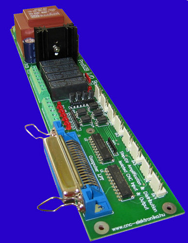
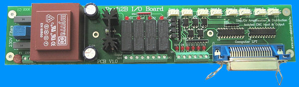
(Profi2B I/O Board)
Modified: kedd, 2009. szeptember 01.
![]() Please
see new version: Profi2C Breakboard!
Please
see new version: Profi2C Breakboard!![]()
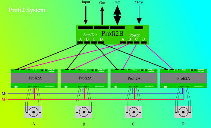
It is the base card of the Profi2 controller family. Its task is to make
connection between the PC and the specifical axis drivers, as well as handling
of the power supply voltages and I/O ports.
Profi2B I/O card makes possible to connect
Profi2A Axis Driver to the
printer (LPT) port of a PC. Maximum 4 pieces of Profi2... can be connected to a
Profi2B controller. The card also contains the digital power supply voltages of
Profi2A besides the amplified and distributed Step/Dir signals. The card
contains all the possible (those of PLT port) inputs and outputs for general
control purpose (end-position switches, digitalisers, mill motor controls,
etc.).
The I/O card can be used with other standard Step/Dir controller too. It does not invert the TTL signals. It can be a basic device for running even mixed mode (stepping motor and servo) controllers at a time.
Technical specifications:
- 8-bit, amplified, Schmitt-trigger-type and distributed Step/Dir TTL outputs (for 4 controllers).
- 5 pieces inputs, which are Schmitt-trigger-type and separated by an optocoupler.
- 4 pieces potential-independent relay outputs (max. 230V, 2A with unipolar separation).
- LED display for the full I/O port.
- Power supply filter on the 230V side.
- Positioned terminals for the power supply and signals (the later are shielded).
- Industrial-level noise protection and build-up.
- I/O connections on swrewed terminals.
- Power supply (control voltages) with short circuit protection.
- Centronics LPT cabel connection (it can receive the standard two-way printer cable).
- Digital power supply (5V, max 1A),
- Bridge voltage (11V, max 500mA).
Mechanical build-up and installation:
(CNC I/O handling)
The size of the PCB of the I/O base-card is 275mm × 55mm. It is a two-sided
electroplated partly SMD PCB. There are 6 pieces (3.5mm diameter) of fastening
holes. All the fastening holes must be used (so that the card could not bend)
because of its longish form.
The ideal place for the card, - taking into account the given length of the
signal connection cables, - is under the block-like placed Profi2... (axis
controller) controller,
placed horizontally.

Here the block-like arrangement of Profi2... can be seen. The Profi2B card can be placed before and under the card in transversal direction.
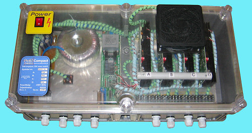
(Profi2 Compact)
Electric connections:
The outer connections (230 V power supply voltage, peripherial connections) can be found separately at the bottom of the card, all them are on screwed terminals.

(4 outputs, 5
inputs under, with full back indication)
The relay outputs contain potential-independent closing contacts. The
maxmimum load of the contacts is 230V and 2A, (unipolar type). Their connections
are: SK1-SK4 (written onto the buttom of the PCB).
The high potential point of the inputs are connected by optocouplers (the power
ground points are connected to GND). Each input has a pull-up resistor. The
mechanic push-buttons, switches can be used directly. All the inputs are
Schmitt-trigger type.
Each input and output has a LED back indication.
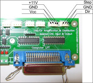
The internal connection points (toward 4 Profi2A Axis Driver, power and signal connections) can be found on the top banked into groups as positioned shielded pin line connections.
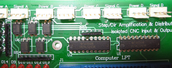
(Axis controller
connections on the top)
(Allocation of
power and signal connections)
These are TTL-level outputs and can have maximum 20 mA current load. They can
be used for other control-purpose too.
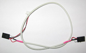
The internal connections were designed for the so-called CD-ROM audio cable,
which is used in the PCs.
(Signal and Power
cable, CD-ROM audio cable)
The use of these shielded and positioned cables is strongly recommended. From the cables only the cables with wide cable end can be used.
Wires with a cross-section of maximum 1.5 mm2 can be connected to the screwed terminals of supplying voltage ( ~ 230V, 50 Hz) and peripherals (end-position switches, motors, relays, valves, etc.), which are placed at the buttom of the card. The recommended cross-section for the wires is 0.5 mm2 .
The outputs are potential-independent closing contacts (they close at the
logical level of 1). Its maximum load is 2A at maximum 230V AC.
The inputs are separated by optocouplers and designed for closing contacts. The
closing contacts must be connected between GND (SK15 = GND) and the inputs (SK10
- SK14). The current flowing through the contacts is about 10mA, its voltage (in
open state) is about maximum 15 V.
The inputs are inverted (in closed position 0 can be read). Each input is
Schmitt-trigger type (with a well-defined kipping point).
Pay attention!
On the lower power supply and relay adapters (depending on the application)
dangerous voltages (230V) may also be present. Special care must be taken when
working with them!
The mechanical fastening of wires of the power supply (230 V) and the peripheral devices is necessary (e.g. when the device is built into a box, the usage of staffing box is necessary ).
For the ready-mounted controller unit (Profi2B + Profi2A) mechanical protection (e. g. building into a box) must be provided).
Software (logical) installation:
The power and signal adapters on the top of the I/O card are for the connection to the single Profi2A axis controllers. These adapters are marked with letters from A to D. These letters identify the axes that belong together (e. g.. A=X, B=Y, C=Z, D=rotating, etc.).
(Connection between the base card and the controllers)
It is worth writing their identification marks onto the controllers (Profi2A). By doing so, later the identification by software will also be easier. Information on the connections of Profi2A controller can be found here.
All the inputs and outputs of the Profi2B I/O card (even the Step/Dir outputs) can be tested by software with the help of Mach3 PC CNC software.
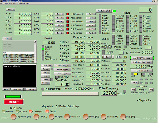
(Diagnostic screen of Mach3 Diag)
The digital outputs of the card can be used not only with axis driver(Profi2...), but they can be freely used, for the control of any other TTL-level control (e. g. PWM rev control of the motor of lathe spindle or PWM control of a filament with the help of Mach3 CNC controller software using additional circuits).
(Using free TTL-level outputs for other purpose)
Configurations from the PC:
The configuration of CNC controller programmes can be found in the description of the specific programme (e. g. Mach2, Mach3,, etc.). If your system is extended with extra LPT ports, then you can find information on putting into operation the devices under the menu Usage of the second LPT port.
(Possibility of extending the system with cards having
external LPT ports)
The adapters of the I/O card can be addressed based upon the base address and the individual pin numbers. These data must be provided for the specific CNC programmes (usually under the port setup menu-item). All the outputs and inputs of Profi2B have fixed bit allocation, which can be seen in the following table:
|
I/O function: |
Terminal/connector: |
LPT pin number: |
|
A control output |
Signal A/Step |
9 |
|
Signal A/Dir |
8 |
|
|
B control output |
Signal B/Step |
7 |
|
Signal B/Dir |
6 |
|
|
C control output |
Signal C/Step |
5 |
|
Signal C/Dir |
4 |
|
|
D control output |
Signal D/Step |
3 |
|
Signal D/Dir |
2 |
|
|
Inputs |
GND |
- |
|
SK14 |
10 |
|
|
SK13 |
11 |
|
|
SK12 |
12 |
|
|
SK11 |
13 |
|
|
SK10 |
15 |
|
|
Outputs |
SK4 |
14 |
|
SK3 |
16 |
|
|
SK2 |
17 |
|
|
SK1 |
1 |
(Bit allocations to be adjusted in CNC softwares)
The construction of the controller gives the end positions to the PC-nek (to the CNC control programme). An example schematic diagram for a 3D system:

(An example for connecting the end positions of a 3D
system)
In the case of this solution the automatic zeroing of the programme can also be performed (recording the zero point even for each axis). It is to prevent overruning the maxmimum end position (all the three axes are monitored at the same time). Of course the proper configuration of the CNC control programme is also necessary beside the connection for the correct operation.
In this solution 4 inputs are used to control the axes (3D), so there is even one free input, which can also be used for other purpose (e. g. for 3 D digitalisation).
![]()