(Bipolar Axis Driver)
Profi2A CNC Controller
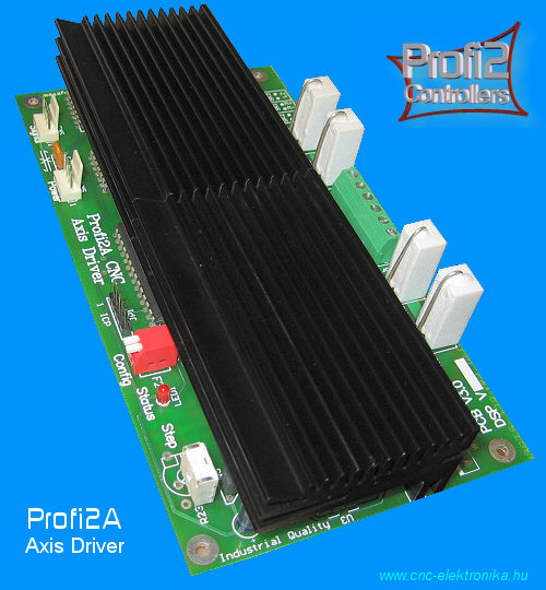
(Profi2A CNC Axis Driver)
(Bipolar Axis Driver)
Discontinued!
Modified: 2009. szeptember 01. kedd
|
Content: |
It is a half-professional carry-out, high power CNC control electronic unit, developed based upon H1 CNC Controller electronic unit. Because of its modular build-up it can be fitted to the actual demands. Controls for 1-4 axes can be built-up for each base card (Profi2B). The number of base cards can be increased for two with the help of suitable CNC control softwares (e. g. Mach3) and CNC machines with maxmimu 6 axes can even be built.


(zoom=click!)
Download:
Demo video:
Rev test (4230 1/min).wmv (5Mb)!
Documentation:
Installation of Profi2A (![]() pdf,
300 kB)!
pdf,
300 kB)!
Technical specification (DSP V1.1):
- Step/Dir system stepping motor CNC controller,
- Modular built-up, one axis for each card,
- Half step system,
- 2-phase, bipolar transmission bridge(with uniform FETs),
- 2-phase, 0.2A - 8A range of controlled motor phase current drive,
- Mixed mode current decay (resonance-free operation),
- Double PWM power control, one for each phase,
- 90V maximum motor power supply voltage,
- A maximum 25-fold, tuning factor
- Signal processing at a speed of 32000 Step/sec,
- Thermal overload protection,
- (Motor power) control with constant moment,
- "Muteable" PWM noise,
- Keeping the motor in holding path (it can be adjusted in three stages by a DIP
switch).
- Dynamic stabilisation of stepping.
- Sinusoid type current control curve (reduction of motor resonance),
- Easy Setup (DIP switch+potentiometer trimmer, fast putting into operation),
- DSP optimalised for Mach2 & Mach3 (pulse memory),
- High-level noise protection (for industrial applications),
- Installed high-efficiecy cooling,
- Sophisticated signals and diagnostics,
- Internal DSP software, which can be upgraded (with the help of ICP, in
service workshop),
- Two-sided, electroplated, partly SMD-mounted PCB,
- Compatibility with Profi2B,
- etc.
![]() General
description:
General
description:
(Modular built-up, one axis for each card)
- Profi2A is a modular build-up, one-axis half-professional controller. In default one Profi2A controller belongs to each motor (axis). The serial connection of two perfectly identical motors is allowed within the load limits (driving in synchronous mode). This method is applied first of all in foam cutter machines. In this case the motors rotate in synchrone.
- Between the Profi2A controller and the PC, a base card, called Profi2B can be found. The task of this base card is to fit the printer (LPT) port of the PC (signal amplification and allocation). On the card Profi2B basic I/O ports (5 inputs and 4 relayed outputs), as well as TTL-level Step/Dir-driven outputs for 4 axes and the digital power supply of the whole system (+5V and +11V) can be found.
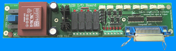
(Profi2B Base Board)
According to that fact, to one
Profi2B base card maxmimu 4 Profi2A controller cardscan be connected. The
system build-up in this way uses one LPT port of a PC and can be a 4D (4 axes)
CNC machnine, which has 5 inputs (e. g. for the end positions, digitalizer, or
for recording the reference point, etc.), and 4 relayed outputs (e. g. for
controlling finishing motor, colling, lubrication, etc.). If more axes or I/O
ports are needed, the PC should be extended with more LPT ports and a Profi2B card, (only the
capability of the CNC controll programme limits the number of units).
Profi2B base card has been designed to handle maximum 4 Profi2A controller
cards.
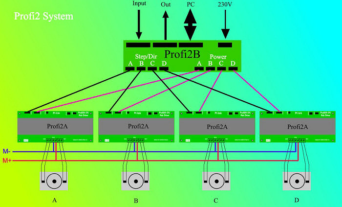
(4D system
build-up)
- Profi2A controller works with standard positiv-logic, TTL-level Step/Dir signals, so movement controllers made by other manufacturers can also be used (e. g. Maxstepper, USB-Step/Dir generator, RS232, etc.).
- The type of the two-phase stepping motor that can be applied:

- Bipolar motors,
- Unipolar motors (with bipolar connection),
- 8-wire, universal motors (bipolar ones, in paralell connection).
Comparing a unipolar and a bipolar motor, the moment of the bipolar motor is
about 40 % higher than that of the unipolar one. The use of bipolar motors is
preferred.
The tuning factor* of Pofi2A Controller is depending on the inductivity of the
motor applied and can be 6 - 25-fold. This controller needs a minimum of 6-fold
tuning voltage.
The lower is the inductivity of a motor, the higher is the tuning factor that
can be applied. The following table helps with selecting the maximum-suggested
voltage of the motor power supply:
|
Base voltage of the motor : |
Recommended power supply voltage: |
|
1V |
25V |
|
2V |
40V |
|
3V |
50V |
|
4V |
60V |
|
5V |
70V |
|
6V |
70V |
|
8V |
80V |
|
9V |
65V |
|
10V |
50V |
|
11V |
40V |
|
12V |
30V |
|
etc. |
... |
![]() Pay
attention! Above 50V special care must be taken! The adherence to the
prescriptions of electric shock protection is compulsory (dangerous voltage)!
Pay
attention! Above 50V special care must be taken! The adherence to the
prescriptions of electric shock protection is compulsory (dangerous voltage)!
- The maxmum motor power supply voltage that can be connected is 90V! The
continuous current load, which can be handled by the power transmission FET
bridge is 8A/phase! Operating near the mamimum load care must be taken of an
intensive ventillation (provided by fans).
During stepping the frequency of the variable duty cycle PWM signal generated by
the controller is 20kHz, so it will produce a voice in the motors, which cannot
be heard by ears ("dumb PWM"). The PWM frequency decreases in holding path stage
(in standing position), therefore a faint voice might be heard in standing
motors (it can be adjusted in three stages).
The holding path excitation (force holding in position) can be selected via a DIP switch. After each change the controller must be restarted!
The DSP software upgrades can be performed through the ICP adaptor (only in service workshps).
Status LED signals:
Operation signals:
The specific holding path excitation adjustments can also be checked by flashing
of the Status LED. The ratio of the length of dark and light periods reflects
the force of the holding path excitation (by raising the excitation the length
of the light period increases).
If the controller is supressed (it is made to be switched off) the LED does not
light at all.
Error signals:
- During each start the controller checks each FET of the power transmission
bridge. In case of error it prohibits any further running and indicates this
error by fast flashing of the Status LED! In case of this signal the controller
must be put out as soon as possible (first of all the power supply of the motor
must be switched off)! After that the controller must be sent for servicing.
The motors does not have to be connected to run diagnostics (it works without
motors too).
- The power transmission bridge of the controller is equipped with thermal
protection (overload protection). The central processor monitores it continually
with the help of a sensor. If the temperature of the heat sink rises up to about
. 75°C, it will switch off the motors and indicates the situation through the
Status LED. In this way it protects the bridge. The protection is not suitable
to protect against short circuits! The state (overheating) is indicated by quick
flashing of Status LED.
In such a case the controller must be switched off and the operator must wait
until the unit cools down and then the unit can be started again.
There is a substantial difference in the speed of flashing of the two signals. Beside that the quick flashing during operation always indicates only the thermal protection, while the very quick flashing during switching on the cold controller always means faulted FETs.
Further developments:
- Profi2A controller implements a special current control (which varies
depending on the phase position and time) with the help of DSP* .
In the half-step system the sinusoid type of driving method produces a smoother
stepping than the traditional (square current generator) control, therefore the
motor resonances decrease in a substantial extent. With the help of this method
the moment of the motor can be increased with 10 % at lower speed. Because of
the mixed mode current decay control the quality of running is extremely good
(improving further the efficiency of resonance reduction).
- The controller has an Easy Setup. It means that only one potentiometer trimmer must be adjusted before putting the unit into operation and the controller is ready for work By the potentiometer trimmer the nominal current of the motor should be adjusted, but the exact adjustment is not essential. The electronic is not sensitive for the exact adjustment (it is linear and tolerant), so the check by a measuring device is not necessary.
- The controller has been optimalised to the control softwares of Mach2 & Mach3 CNC controlling programmes. The DSP application running in the processor and a special so-called pulse-memory makes possible to choose an extremely short Dir preselection.
- Because of its industrial build-up the controller has a strong noise protection, which can be increased to the maximum by proper installation (mounting)! The version built into a case has this high-level protection.
(Logical schematic)
*Tuning factor: determines the maximum power supply voltage applicable to a given motor in the function of the base voltage of the motor (Upower supply=Umotor× Tuning factor).
*DSP: Digital Signal Processing.
![]() Installation, putting the unit into operation
Installation, putting the unit into operation![]()
(detailed description)
Mechanical build-up, placing:
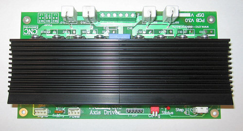
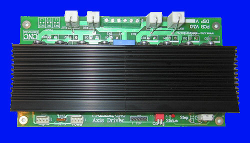
PCB:
- Two-sided electroplated PCB, with partly SMD mounting,
- Sizes: 170 mm×90 mm, height demand min. 50 mm (with ventillation),
- 4 pieces of 3.5mm diameter hole for the fixing screws, in 159×79mm spacing.
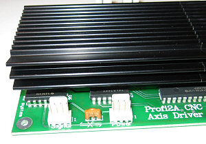
(PCB)
The optimal placing of the controller is setting it on the edge (mounting the cards on the top of the other one) to achieve the lowest demand on place. The block should be build-up in a way that provides free unobstructed ventillation. The optimal build-up of the controller is a block-type build-up with cards in a position set on the shorter edge mounted with spacers on the top of the others, To fix the items use spacers made of metal.

(recommended block-type build-up and its ventillation)
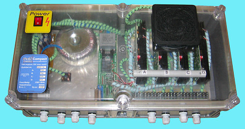
(Profi2 Compact)
Place the unit farthest off from (electric) noise sources. Protect it from dust and mechanical effects by building it into a case (but take care of providing proper ventillation). Do not expose it to any mechanical shock.
Above 5A /phase current demand forced cooling is necessary (by fans).
Electric connections:
All wires should be shielded mounted.
Wires with high current (connections of the power supply of the motor and phases
of the motor) are led to screwed terminals. The applicable wire-cross-section is
maximum 1.5mm2. It is recommended to have all the high-current wires
as shielded, twisted pairs. The 4-wire so-called 4-20 mA industrial signal
cabel, which is in the form of 2 shielded twisted pairs is suitable for this
purpose (it can be purchased in electric shops).

(2×2 twisted pair
with a cross-section of 0.5mm2)

(one twisted pair = the two ends of one motor-coil, with
common shielding)
According to one shop, the denomination of the cable is GJY STY and it is available with several cross-sections (0.5mm2 is suitable). Its price is 0.32~0.4 Euro/m +VAT
Special care must be taken of connecting the right polarity (power supply of
the motor)! In case of wrong connection the controller damages!
The high-current wires should be placed the farthest off from the controller.
The connection of the digital power supply and signals are pin lines. The pin lines were designed for the so-called internal CD-ROM audio cable, which is used in the PCs.The use of these cables is strongly recommended (at both ends with wide black connector). The connections are position-marked, reverse connection is not possible.
(Signal and Power
connections)

(Shield cabel)
Care must be taken not to swap the Signal and Power lines. In case of wrong connection, the controller may damage badly at once.
The shield of the lines cannot be an active line (no current must flow through it). All the shields must be connected to the digital minus (GND or M) of the system (on the Signal and Power terminals these are automatically carried out). Care must be taken to avoid the so-called earth-loop. The wires with high current must be separated from the signal lines as much as possible.
The wires should not be in contact with the heat-sink (danger of melting).
To one
Profi2B card (base card) maximum 4 Profi2A motor controller cards can
be connected.
The card
Profi2B provides the digital power supply voltages (+5V and + 11V)
for Profi2A Controller cards, as well as amplified Step/Dir signals. Beside that
it has 5 inputs and 4 relayed outputs (which can be freely used).
The I/O lines must be mounted with shield. The wires with high current must be
mounted as twisted pairs (wires of motors and power supply of motors). For the
small-signal lines (Signal, Power) the use of the internal shielded audio-cable
used in PCs is suggested.
(Profi2B I/O Board)
The four Profi2A Controllers must be marked from A to D. It is worth writing
the controllers’ marking onto them using an alcoholic brush-pen. Later the
assignment of the bit allocation table to the controller can be done based upon
this marking.
The Signal connection of Profi2A must be connected to the Signal connection of
Profi2B Signal.
The Power connection of Profi2A must be connected to the Power connection of
Profi2B . In case of the power supply connector the marking has no special
role.
As for as the power supply of the motors, it is possible either to feed all
the motors with the same power supply, or to use separate power supply for each
motor (in the later case the minus terminals of the motors must be connected
together).
The digital GND (Profi2B) and the minus terminal of the motor power supply must
not be connected together outside the controller (they are connected together
inside Profi2A Controller)!
Before selecting the power supply voltage of the motor, it is worth reading the Description of Tuning of Profi2A, which may give the user tips for the correct selection!
The power supply voltage of the motors does not need to be stabilised, but
must be filtered by a capacitor of 1000uF/A (oversizing the capacitor is not at
all harmful). When calculating the load current of the motor, the phase current
of the motor must be taken into account (in case of common power supply the
summarised value of each axis).
Only a 6-fold of tuning voltage is suggested.
Connection of the Motoros:
(Motor and Mator Power connections)
- The controller has been designed for two-phase bipolar (4 terminals)
motors.
In case of bipolar motors the matching phase-ends must be connected to SK2 (L1)
and SK3 (L2). The power supply of the motor must be connected to SK1 (with the
right polarity). The phase sequence does not matter, the CNC software can change
the direction of the rotation.
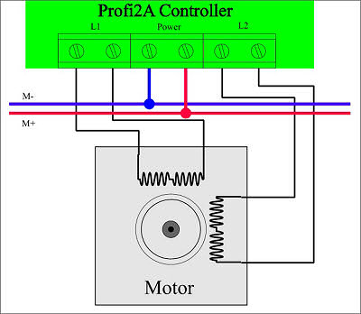
(Connection of Bipolar motors)
- In case of universal (with 8 terminals) motors the coils should be paralell connected in pairs (i. e. the coils belong to the same phase should be paralell connected). Higher moment and better ability of tuning can be obtained in this way.
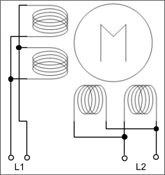
(Connection of 8-wire motors)
In this case the motor current to be adjusted is twice as much as the coil current.
- It si possible to connect unipolar motors too. In this case there are two possiblities:
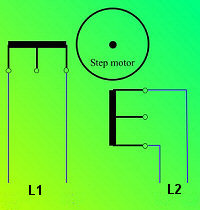 |
 |
| A | B |
|
(Possibilities of connection of Unipolar motors) |
|
There are substantial differences between the two methods of connection.
Methode A: a moment 20 % higher can be obtained at lower speed (twice as mush of windings are excited), but the maximum speed at the same voltage is substantial lower (because of the 2-fold inductivity). The inductivity and the base-voltage of the motor is twice as much as the factory specification. The nominal current to be adjusted is the nominal current of the coil.
Methode B: all the parameters are the factory specification (higher speed, nominal moments). The current to be adjusted is the same that is indicated on the motor. It does not matter which end of the coil is connected together with its center terminal to the controller (it determines only the direction of rotation). This method of connection is preferred!
- The serial connection of two motors for one axis and their synchronous driving can be realized too:
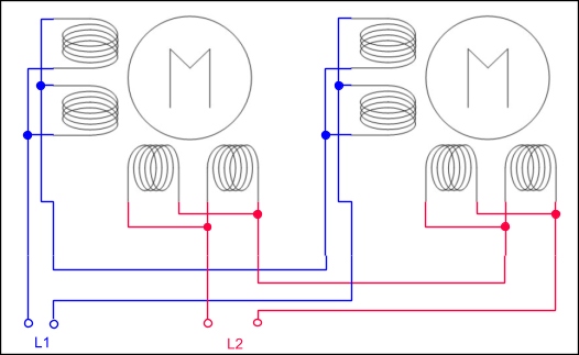
(Two motors in one axis)
Only motors of the same type are allowed to be serial connected. In this case the resultant motor is a motor with a voltage (and inductivity) twice as much as that of the base motors. Its ability for tuning is worse than that of with only one motor.
In case of applying Mach3 software the logical assignment of the axes can be realized (Slave modes) and their full synchronous driving too, in this way two-motor driving for each axis using the controller only with one motor can also be realized.

(logical assignment of axes)
More information on tuning of the motors and selection of the motor power supply voltage can be found in Description of tuning.
The power supply of the motors must be protected by suitable
fuses (serial connected with M+ ).
The digital power supply (on the Profi2B card) is protected against
short-circuit.
Adjusting the motor-current (Step trimmer):
Before connecting the controller to the power supply the following steps must be performed:
- The connections (their place and polarity) must be checked and it also must be checked whether the motor-circuit is free from short -circuit (the controller is not protected against short-circuit).
- By the means of the potentiometer trimmer STEP (R23) the nominal current of the motor must be adjusted. With the help of a small-size screw-driver turn the potentiometer trimmer gently to clockwise direction and observe its end position. In this position the controller would regulate to about 0.2A.
Then turn the potentiometere trimmer to counter-clockwise direction and observe this end position too. At this point the controller would regulate to 8A.
Now divide up the angle range and estimate the position of the nominal current of the motor, then adjust the arrow-form pointer of the potentiometer trimmer to this position.
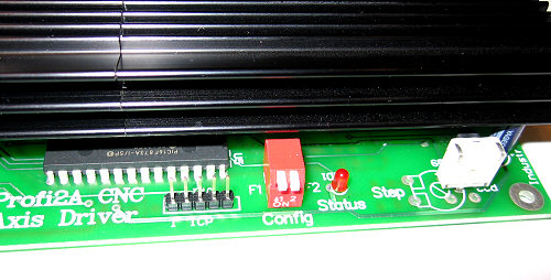
(Config DIP and Step Trimpot)

(Step trimpot)
The controller is not sensitive for the exact adjustment. During operation the position of the potentiometer trimmer can be changed at any time (observing the voice and upwarming of the motor).
The controller holds motors standing by reduced excitation in position.
This force (excitation) holding the motor in position can be adjusted in three
stages. These values are preprogrammed values, from them the intended value can
be selected by the means of a DIP switch..
From the preprogrammed values the correct one is the value, which can hold the
motor safely in position using the lowest excitation (even in half steps). The
force holding in position can be chacked even by hand if you grasp the end of
the axis in case of a motor standing but switched on and you try to move it. The
motor must produce a well-defined but not too high force.
In the course of holding path excitation the frequency of the excitation current
is also reduced so that the core loss could be reduced. This is done by
software-based PWM modification, which produces an audible voice in the motors.
This is absolute normal, the motors can cool down better in return.
The holding path excitation (the force holding in position) can be selected by the means of a DIP switch. After each change of the switch, the controller must be restarted!
On the DIP switch (Config) the following adjustments are possible:
|
Force of the holding path: |
F1: |
F2: |
|
Low (base adjustment, recommended) |
Off |
Off |
|
Middle |
On |
Off |
|
Full excitation (dumb mode)* |
Off |
On |
|
Spare |
On |
On |
(Config DIP positions)
*In the full excitation mode there is no holding path PWM noise (dumb mode ). In this case the motor is tanding with full (STEP)excitation! Its use may cause strong upwarming in the motor (special care must be taken).
At this point Profi2A controller is ready for CNC operation.
The configuration adjustments on the PC-side of the controllers can always be found in the documentation of the applied base card (in case of Profi2B interface card the description can be found on my WEB-page)!
Usage:
The controller indicates the given status by different (Status) LED signals. The flashing of the status LED reflects the selected holding path force (greater force is indicated by a LED lighting longer.).
At the time of switching on, the controller performs a self-diagnostic procedure and it will enter to Online mode when the FETs are perfect. If the Status LED begins to flash very fast after switching on, it means that one or more FETs became faulted. In this case the controller must be switched off and must be taken to a service station.
In the course of normal operation of the controller (in Online mode) the
Status LED indicates that everything is „OK” by short flashes.
If the LED changes flashing to quick short uniform flashes, it means that the
protection works and the FET-bridge has overheated. In this case the controller
stops further motor excitation (switches off). This will last until you switch
off the controller and wait until the heat sink of the bridge cooles down.
This phenomenon refers to overloading or insuffishent ventillation. This signal
can only be cleared by restart.
The excitation of the motors can also be adjusted during operation. By observing the voice of the motors (at relatively slow revolution, e.g. at 500..1000 step/sec) the force of the excitation can be tuned (usually it is the most silent or the smoothest when the most suitable value is applied).
The speed of the motors, the direction of rotation and the acceleration (and several other parameters) must be adjusted within the applied CNC controller programme (see e. g. Description of Mach3).
Further additional information can be found in the description of
Motortuning of Profi2A .