(3D, Compact, PWM-type current-controlled, Stepping Motor Controller)
![]() H1
PCB CNC Controller
H1
PCB CNC Controller![]()
(3D,
Compact, PWM-type current-controlled, Stepping Motor Controller)
Modification: 09.01.2009
|
Content: |
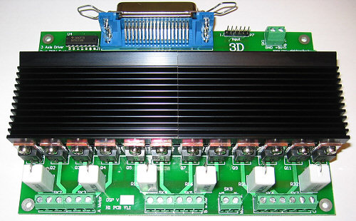
H1 CNC controller is a compact and economic electronic unit developed based upon the working principles of Profi2A controller. Because of its concepts, it is able to operate already after connecting relatively few components (power supplies, end positions and motors). The controller is of a three-axes type, and contains the basic inputs and outputs as well as some parts of the digital power supply (its stabiliser and filters. Its power transmission optimised to the motor speed (FET power stage with ultrafast decay) makes possible to reach the adjusted speed value very quickly.

H1
Promo video (wmv, 4.66MB)
Versions:

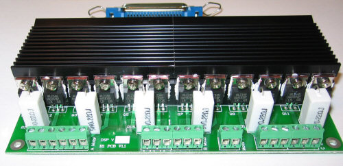
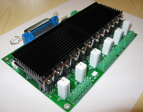
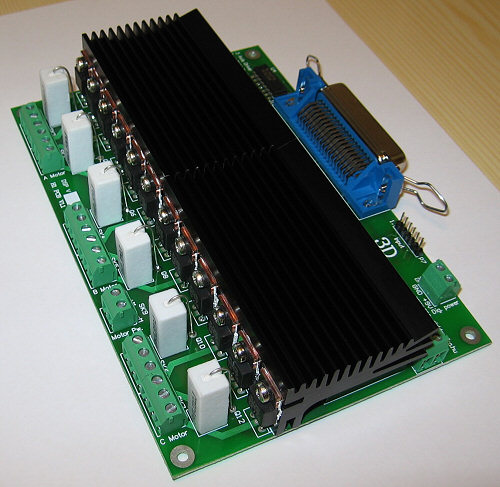
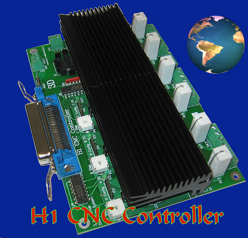
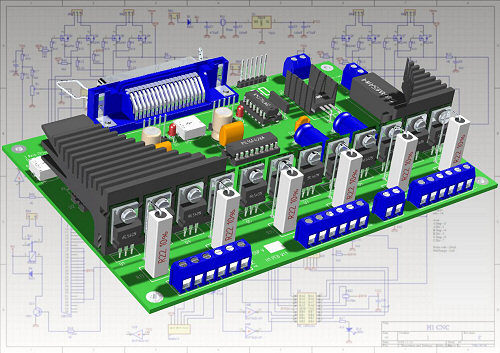
| H1 PCB Controller: |
|
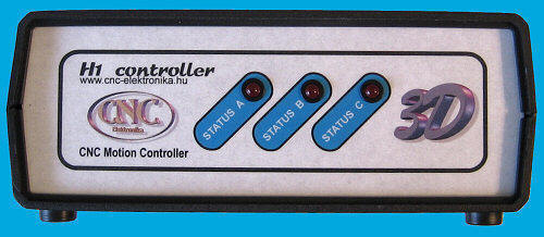
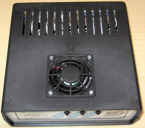
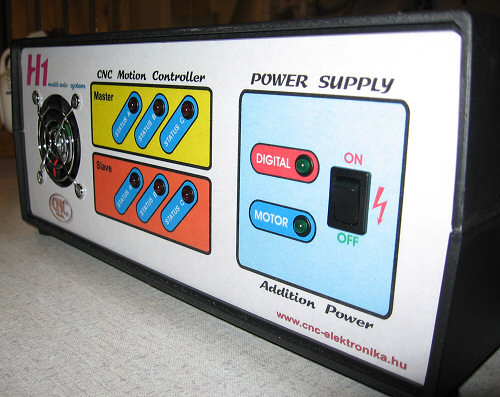
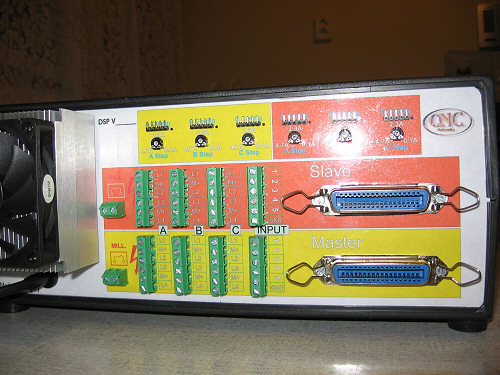
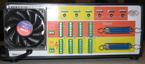
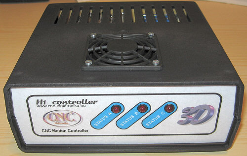
| H1 CNC Controller in Case: |
|
|
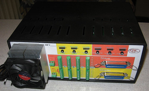
H1
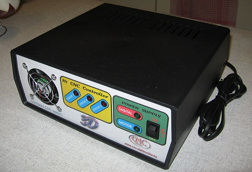
Compact CNC Controller: (with Power Supply) |
|
|
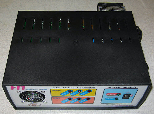
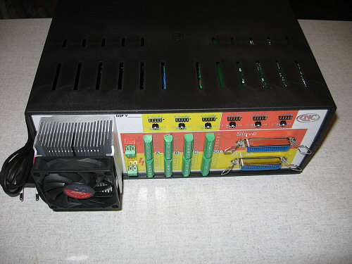
H1
Multi Axis CNC Controller: (with Power Supply) |
|
(Zoom=klikk)
(H1 PCB Test Video, wmv, 12MB)
Main technical specifications (DSP V1.4):
- 3 axes type (3D), Step/Dir system, CNC controller, for stepping motors,
- Unipolar, 2 phases stepping motor driving (FET power transmission with ultra fast decay),
- Half-step method,
- Power stabilisation by controlled PWM method (by the use of DSP* algorithm),
- PC communication by standard two-way Centronics printer port (LPT),
- Motor current adjustment for each axis by the means of a potentiometer trimmer,
- Motor current controll range of 0.1A - 4.7A /phase, for constant motor power,
- Maximum motor power supply: 50V,
- Maximum tuning factor: max. 25-fold (depending on the inductivity of the motor),
- Automatic control of the motor current in the holding path (by software),
- envelop with a sinusoid-type current control, so that the active motorresonance could be reduced,
- Holding-path torque, which can be adjusted in 3 stages during Setup,
- Easy to take it into operation (Jumper Setup),
- "silent" PWM mode selectable,
- Stepping power is over 35000 Steps/sec for each axis,
- Independent DSP signal processing for each axis (3 independent high speed controlling with constant torque),
- Complex display by LEDS for each axis (Setup statuses),
- Automatic FET's transmission diagnostic (POST),
- 1 relay output (max. 230V, 3A),
- 5 pieces Schmitt-trigger type input forwarded toward the PC (for processing by the means of software),
- ICP connection for each axis (Firmware/DSP update possibility),
- Optimised algorithm for Mach2 & 3,
- Excellent cooling,
- Increased interference and noise protection,
- Two-side, metallized, partly SMD mounted PCB,
- WinPC-NC software compatible.
*DSP= Digital Signal Processing .

(SMD mount)
![]() General
description:
General
description:

(Controller
in-case-built-in)
H1 CNC Controller can be used to control machines with 1, 2 or 3 axes (it is not necessary to work with all three axes at a time). The paralell connection of 2 pieces NOT recommend!
The motors driven by the controller can be 2 phase and unipolar type (with 5, 6 or 8 terminals).

(motor connect)
To run the controller, a power supply with two output voltages are necessary:
I. An output voltage of 9-15V DC, filtered at least with a capacitor of
1000uF for the digital circuits (maximum current load: 200mA),
II. A (filtered) DV voltage matched to the stepping motors.
The two kinds of voltage should come from two independent transformers (or at
least from independent coils of one transformer). The electric noise made by the
motor should not get to the digital supplying voltage.
Neither of the power supplies need to be stabilised, but rectifying (DC) and
proper filtering with capacitors is necessary. The system should be
fault-protected with fuses.
More can be read about the selection of motors and their power supplies on
H1
Tuning.
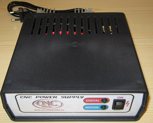
(power supply for
H1 controller)
The new H1 controller can be used with the old power supply (24V) of Profi1.
The Controller performs current control according to the actual current consumption of the motor, phases of stepping as well as stepping time for each axis. The stepping system is a half step one, so the resolution is duoble of the base value. The exact control value (depending of the motor) can be adjusted by the means of 3 pieces of pontiometer trimmer (one for each axis). Because of sinusoid-type envelope current control of the internal processors (DSP) the the resonance of the motors is damped in an active way.
The control results a constant power and constant torque consequently. The
controller depending on the motor (inductivity) can be really easy tuned. The
tuning factor is responsible for the biggest possible constant torque range,
about which more can be read on H1 Tuning.
At the end of the steppings (following a short dinamic damping) the motors get
automatically a reduced excited state (holding path). It is necessary because of
holding in fixed position (the position must be kept even in half stepping
position). In the course of keeping in position the motors are in a state of
rest, the extent of the excitation, - and so the torque, - can be adjusted by
Setup). These values (reductions) can be selected from a preprogrammed set in
three stages by the means of a jumper. A holding path current reduction
decreases according to the stepping value, so its value changes proportional to
the adjustment of the potentiometeer trimmer (% reduction).
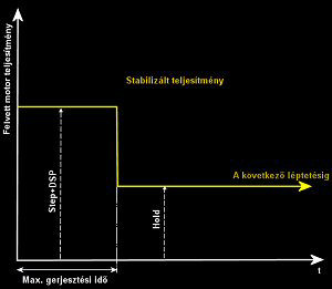
(Holding torque)

H1 Controller has 1 potential-independent relay output with operating contact
(MILL terminal). This relay can switch a current of maximum of 230V and 3A. It
can be freely used, with the help of a PC CNC software programmes (eg. to start
a mill-motor, to switch the heating of the cuttung wire, etc.). It is controlled
by PC software programmes (see the possibilities of Mach3 ).
The controller has 5 pieces of Schmitt-trigger-type inputs (connector P7). These
inputs are prepared for operating contacts of mechanic type. Any type of
microswitch can be connected to them (to switch to the common GND). They can be
used as end position switches, for automatic recording of 0 position, for
digitalisation, etc. The state of the inputs is procesed by PC software
programmes.

The controller communicates with the PC by a two-way printer (LPT) port. As a
connection cable a normal (two-way) printer cable (its recommended length is
maximum 3 m) can be used. In the BIOS SETUP EPP (or SPP) mode should be
selected.
Any kind of CNC controller software can be used, which meets the following
requirements:
- Suitable for Step/Dir type axis control,
- Communicates through an LPT port,
- Its bit allocation can be freely adjusted,
- Does not need an outer, so-called impulse generator.
Some of possibly suitable programmes: Mach3 (recomended); Mach2; KCam4; TurboCNC, WinPC-NC, etc.)!
(Mach3 CNC controller software)
Minimum Step/Dir timings of H1 Controller:
Width of the Step signal: min. 20uS
Tracing of Dir signal: min. 5uS
The most suitable for this task is Mach3 CNC controller software (even the controller has been optimised for that).
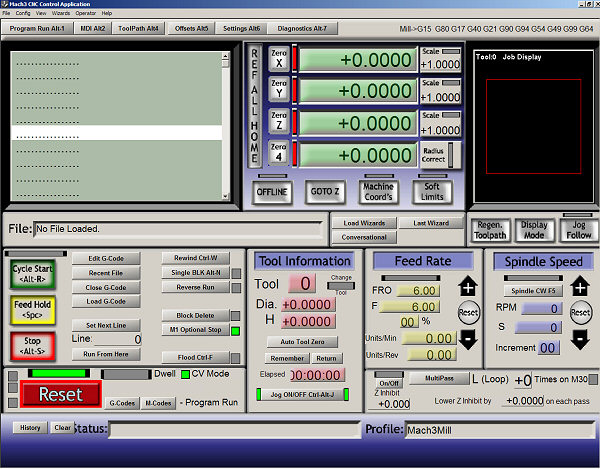
To test the inputs and outputs, the most suitable is to use the diagnostic screen of Mach3 v. 2:
![]() Taking
the controller into operation (in case of ready-mounted and tested controller):
Taking
the controller into operation (in case of ready-mounted and tested controller):
Mechanical arrangement and placing:
PCB version:
The Controller is built up on a two-sided metallized board with the size of
170�115mm. The PCB is fixed against and tension by 4 pieces of 3mm screws. For
the secure fixing 5mm diameter spacers made of metal or plastic should be used
between the PCB and the fixing surface.
The controller warms up more intensively than the old Profi1, therefore care
should be taken of a better cooling. Up to 2A the natural venting almost
suitable, above that (maximum up to 4.7A/phase) fans must be used. The heat sink
(because of noise protection) is connected to GND potential.
In the course of designing natural venting the direction of finning of the heat
sink should also be taken into account (to ensure chimney effect).
When connecting the terminals prove a support by your hand.
When choosing the cross section of high current wires, the terminals of the
motors are authoritative.
Breakpoints should not made on the terminal of the controller, they should be
made on a separate terminal with a suitable size.
It is not necessary to use shielded cables, but there are parts where their
application is recommended, such as inputs of the end positions, digital power
lines. The shield should be connected to GND (available on the connector P7). No
current should flow in the shield.
At the input connector (P7) a female connector should be used (direct soldering
is not suggested).
In the case of incapsulating care must taken that the potentiometer trimmers
adjusting the excitation of the three axes (Step) could be adjusted by a
small-size screw driver during the operation (usage).
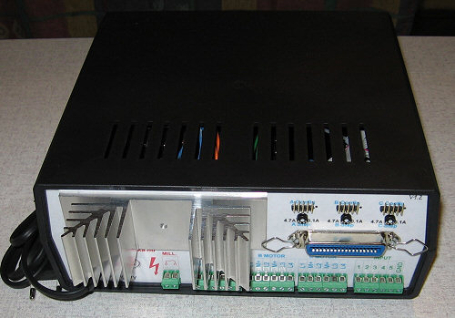
Controller in-case-built-in version:
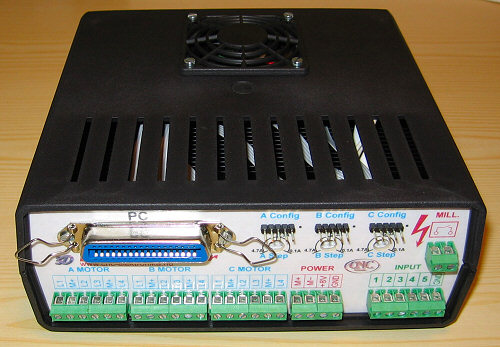
(All connections in socket)
Power supply:
Two voltages are necessary:
- Digit�lis power voltage, its terminal point: SK1, polarities marked,
- Motor power voltage, its terminal point: SK9, polarities marked.
The power supply of the controller is an unstabilised filtered (minimum by a
capacitor of 1000 uF) DC voltage of 9-15V. The current consumption of the
controller is max. 200mA.
The power supply of the motors is also an unstabilised, filtered (minimum
capacitor value is 1000uF /A) DC power supply matched to the voltage and
current demands of the motors applied.
The Chopper circuit of the controller need a higher voltage, therefore tho
motor voltages should be carefully choosen.
Recommended motor supplying voltages as a function of the base voltage value of
the motor:
|
Base voltage: |
Recommended supplying voltage: |
|
1V |
25V |
|
2V |
40V |
|
3V |
40V |
|
4V |
28V |
|
5V |
25V |
|
6V |
24V |
(recommended motor voltage selector)
Motors with voltages between two values (eg. motor of 1.25V), the proportional value of the two neighbouring values (25V and 40 V) must be taken into account (eg.: 1.25V=28.75V). In such cases the biggest value which is even smaller than this voltage (24V in the present case) must be choosen for supplying volatge (a voltage of 24 V can be as high as 33V without any load after rectification and filtering).
When motors with different base voltage are used, the tuning voltage belonging to the smallest base voltage must be applied.
The recommended power supply can be seen here.
Care should be taken of the fault protection of the power supplies (eg. by the means of fuses). Only standard safety insulating tranformers can be applied for that purpose (electric shock protection).
Switching power supplies (such as ones used in PCs) are not recommended (they are PWM noise-sensitive).
The negative end of the digital power supply and that of the motor power supply should not be connected (because of noise protection reasons), they are connected within the controller.
Take care of the polarity and proper connection of terminals. In case of reverse polarity or wrong connection the controller can go wrong immediately.
If it is possible (but is not essential), all wires should be mounted with shield (the shield must be connected to the GND of the controller). The shield must not be used as an active wire (no current may flow through it).
Connecting and adjusting the motors:
The cross-section of the motor terminals should be taken into account, when
connecting the motors. The possible shortest wires should be used (source of
noise). Take care that the connections and isolation must be unharmed, because a
fault may cause the controller to go wrong.
Connections:
- Motor A: SK2 and SK3 (coil groups 1 terminal),
- Motor B: SK4 and SK5 (coil groups 1 terminal),
- Motor C: SK6 and SK7 (coil groups 1 terminal).
It is not necessary to use three identical motors. In the course of the selection of motors it must be taken into account that they will be powered by the same power supply, (see the description of Tuning H1), and their added current demand must not exceed the current limit of 4.7 A/phase, as well as they should be a type of two pahse unipolar (or can be connected in that way) with 5, 6, or 8 terminals.
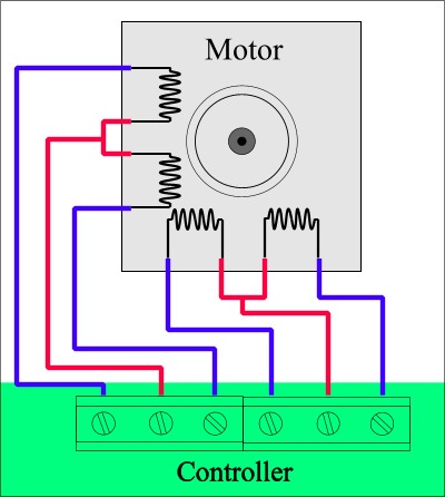
Motors of type of A 2 phase, unipolar with 6 terminals must be connected in the following way:
(6 wires motor)
The matched winding ends can be searched by resistance measuring. Swapping
them, causes erratic steps.
There are motors of this type with 5 terminals too. In these motors the middle
of the two coils are inside commoned and led to the terminal as one wire. These
motors must be connected in the same way, only the only the moving contact
termination must be connected to the place of any of the moving contact
termination (it is marked red on the drawing). The phase selection (by using a
measuring device) is not unambigous (because of the internal conncetion),
therefore the search for moving contact termination can only be done
experimentally.
Two-phase motors with 8 terminals (type of universal) must be reconnected first (as unipolar) according to the type of ones with six wire. After the connection of the matching coils they must be connected similarly.
(8 wires motor)
It is extremely important to connect the matching coils, because there is only one correct connection, (in all the other cases the motor does not step). The specifitaions sheet of the motors should be used for identification of the ends.
Using two motors with one (common)axis:
If it is necessary, two motors can as well drive one (common) axis. To do this, the motors should be totally uniform with 8 wires (universal motors).

(series connection in 2 motors)
The equivalent coils of the two motors should be in serial connected. The motors connected in the way presented in the figure will rotate in the same direction.
If rotation in a contrary direction is necessary, then (only) the two coil-ends belonging to one of the phases of motor No 1 (e. g. violet � green) must be interchanged.
Please see all informnations in H1 Motortuning description!
Adjusting of the motors: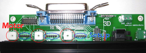
Before connecting the controller to the power supplies the following must be done:
- It must be checked whether the connections are correct (their place
and polarity should be checked) and if the motor-circuit is free from short
circuit (the Controller is not protected against fault)!
- The nominal currents of the motors must be adjusted ont he STEP (A Step, B
Step, C Step) potentiometer trimmers. The motors will be excited by these
currents during steps. By the means of a small screw driver turn the trimmers
gently to clockwise direction to their end position. In this position the
controller would control approximately 0.1 A.
The turn the trimmers to counter-clockwise to the other end position. In this
position the current would be 4.7 A.
Then divide in imagination the angle range and estimate the position necessary
to produce the current your motor needs and put the arrow form indicator of the
potentiometer trimmer into this position.

(Trimmer setup for Step)
The controller is not sensible to the exact adjustment of the motor current
(its linear and tolerant), therefore a check by the means of a measuring
instrument is not necessary (it would not even be simple to measure it). In the
course of operation of the controller it can be gently adjusted at any time when
it is necessary. If the motors have proper cooling this (the current limit) can
even be increased a little.
During normal operation the motors warm up. This warm-up is normal up to about
60~70�C (your hand still can stand the heat). This temperature should not be
exceeded. If the motors warm up very much either the excitation should be
decreased (by turning the potentiometer trimmers to clockwise direction), or
better cooling must be provided (mounting fans to the motors).
The controller holds the motors in position with decreased excitation
(holding path). The force (excitation) that holds the motors in position can be
adjusted in three grades. The decreasement always will be according to the
excitation adjusted by the potentiometer trimmer (% reduction). These
decreasement values are preprogrammed values, from which you can select one by
the means of a jumper (for each motor).
The suitable excitation value is the lowest excitation that securely holds the
motor in position (even in half step). The force holding in position can be
checked by hand: Try to turn of the shaft of a standing (but being switched on)
motor. The motor must develop a definit (but not too large) force against the
turning.
The more effective holding path state the frequency of the exciting current is
also decreased in order to decrease the core loss. This happens by a PWM
modification performed by software, which results in an audible voice in the
motors. This is absolutely normal, and makes the motors cool better.
The holding path excitation (force holding in position) can be selected by the means of Config a jumper. After each adjustment of the jumper the controller must be restarted.
The jumpers (A Config, B Config, C Config) makes possible the followings:
|
Force during holding path excitation: |
Jumper 1: |
Jumper 2: |
|
Small (base adjusrtment, recommended) |
- |
- |
|
Middle |
2-3 |
- |
|
"silent" PWM, Full excitation |
- |
4-5 |
|
Motor switched off |
2-3 |
4-5 |
(Holding setup)
The pin No 1 of the jumpers is marked with a small a white point.
The Config jumpers are ICP connectors at the same time. Through this connection the DSP software updates can be performed (only in a service station).
Signals of the status LED:
After
switching on, the controller performs a test in order to check whether the FETs
(power transmission) are free from short circuit. If a FET with short circuit is
found, the status LED will blink quickly and the operation of the axis this FET
belongs to, will be supressed. In such a case the controller should be switched
off as soon as possible (first of all the power supply of the motor) and you
should proceed as it is described in the Service menu.
The diagnostics is effective only if the motors are connected!
The individual adjustments can be checked by the blinking of the Status LED too.
The ratio of the dark and light periods of the LED shows the force of the
holding path excitation (increasing the excitation, the period of the light
state will also be increased).
If the motor is switched off, the LED will continuely light.
Output:
The terminal marked MILL (SK8) has a potential-independent making contact
(relay). This can be loaded maximum 3 A, at 230 V. It can be used as a switch.
The relay is controlled by the PC (i.e. by the CNC control programme used).
Usually it is configured as a MILL (mill motor) switch, but it can be configured
to any kind of task, what is allowed by the programme. More can be read about
that in the description of the CNC control programme applied.
Possible sample connection:
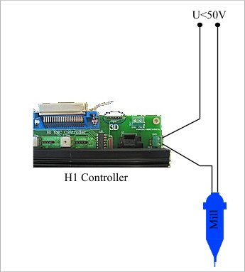
(If Mill voltage < 50V)

(If Mill voltage > 50V)
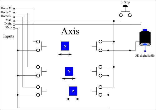
Inputs:
The 5 inputs (connector P7) is prepared to receive making contacts. The common
point of the inputs is pin No. 6 (GND). To connect to the input connector a
female connector should be used.
(Inputs)
A possible sample connection:
(Example)
Athe connection by itself cannot functionate, the CNC control programme must also be configured.
As push buttons, end position switches any kind of microswitches (even a mechanic type) can be applied. These signals are processed by the PC, not by the controller.
The input cables should be mounted shielded.

To run the controller thenecessary CNC control softwares must also be
configured.
All the inputs and output are of non-inverting type, (the LowActive state
should not be ticked in the Mach softwares)!
The following table shows on which pins of the LPT port the different signals will appear. These must be adjusted in the CNC control programmes applied (Found under the Setup or Config menu).
If use DSP V1.3 and down:
|
Function: |
Place/Job: |
LPT pin number: |
|
Motors |
A Step |
4 |
|
A Dir |
5 |
|
|
B Step |
2 |
|
|
B Dir |
3 |
|
|
C Step |
6 |
|
|
C Dir |
7 |
|
|
Output |
MILL Relay |
14 |
|
Inputs |
P7 1. |
15 |
|
P7 2. |
13 |
|
|
P7 3. |
12 |
|
|
P7 4. |
11 |
|
|
P7 5. |
10 |
|
|
P7 6. (Common GND) |
- |
(H1 bit setup DSP V1.3 and down)
Usable softwares: Mach2-3 (recommended), TurboCNC, KCam4
If use DSP V1.4 and up:
|
Function: |
Place/Job: |
LPT pin number: |
|
Motors |
A Step |
5 |
|
A Dir |
4 |
|
|
B Step |
3 |
|
|
B Dir |
2 |
|
|
C Step |
7 |
|
|
C Dir |
6 |
|
|
Output |
MILL Relay |
14 |
|
Inputs |
P7 1. |
15 |
|
P7 2. |
13 |
|
|
P7 3. |
12 |
|
|
P7 4. |
11 |
|
|
P7 5. |
10 |
|
|
P7 6. (Common GND) |
- |
(H1 bit setup DSP V1.4 and up)
Usable softwares: Mach2-3 (recommended), TurboCNC, KCam4, WinPC-NC
Please check DSP version in PCB!
You can freely decide that which motor (A, B, C) to which axis (X, Y, ZX) will be assigned. For the correct operation several other parameters must be adjusted besides the CNC programmes, please study carefully the description of the programme you want to use.
(Recommended software: Mach3 CNC controll program)
![]() Quick setup
II. files for Mach3 RC2:
Quick setup
II. files for Mach3 RC2:
If use DSP V1.3 and down:
- Original screen with end switch: Mach3Mill_vegallassal.zip
- Original screen wihout end switch: Mach3Mill_vegallasnelkul.zip
If use DSP V1.4 and up:
- Original screen with end switch: H1 Conroller_ered.zip
Please control all parameters after setup and modify for You Machine!
Please copy for MachMill.xml or H1 Controller.xml files into instaled folder (ex: C:\Mach3)!
Importan!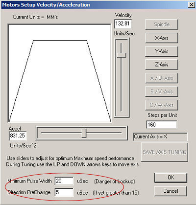
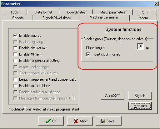
Pulse Width=20 uSec.
Direction PreChange=5 uSec.
When using Mach3 the following must be configured:
Step Pulse=5 uSec.
Dir Pulse=5.
In case of Mach3 it is worth switching on the Sherline 1/2 Pulse mode, this will increase the accuracy and stability of our system.

(Mach3 setup if use DSP V1.4 and up)
If use DSP V1.4 or up:
Usable WinPC-NC software (with fix motor bit map)!

(WinPC-NC CNC controll software)
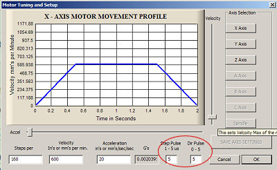
Setup:
(WinPC-NC Step setup)
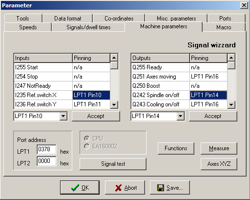
(WinPC-NC I/O setup place)
WinPC-NC axial map: A=Y, B=X, C=Z.
![]()