(theory and practice)
![]() Tuning
of H1 CNC Controller
Tuning
of H1 CNC Controller![]()
(theory and practice)

Modified: 12.12.2006
![]() Using
two motors with one (common)axis!
Using
two motors with one (common)axis!
As in the case of all of the stepping motor drivings the performance (speed) can be increased only by raising the motor power supply voltage. Tuning of H1 is much more simple than that of old Profi1.
![]() Theory
and limits:
Theory
and limits:
H1 CNC stepping motor controlles has a current
regulation based on the Chopper principle, which uses a generator with regulated
PWM duty cycle. The electronics limiting the current tunes the PWM duty cycle
according to the phase currents measured (there is two independent circuits for
each motor, 6 pieces are all together). The stalling point of the Chopper
circuits if determined by the DSP algorithm using a reference voltage generator
as the function of phase, driving mode and time (DSP). The regulation is for
constant motor performance. So as fas as there is enough high voltage from
the power supply, the performance of the motor and its torque is constant.
The torque provided by the motor is porportional to the eletric performance
inputted, therefore care must be taken of the stable and constant performance
input. If the inputted performance decreases, so will the torque of the motor,
if the performance inputted increases, then the motor will warm up (after a
time), (it may even go wrong).
The main reason for decreasing ogf the torque the inductivity of the coils of the motors. The additional electric resistance created by the inductivities, which decreases the current consumption, and so the performance provided, - depends on the frequency and on the speed consequently. The higher is the speed (stepping number) a motor is driven by, the higher voltage is needed (to provide the same torque), i.e. the motor-voltage must be continually increased (with increasing speed) if you do not want the torque to decrease.
This voltage increasement is performed by the controller in a stabilised way
based upon measurements. It can be stabilise the voltage until it equals to the
power supply voltage applied to the motor. If the speed is increased even
higher, the controller will no longer be able to keep the motor performance
constant, and the torque will begin to decrease.This point is the stalling point
of the control.
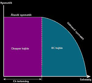
Under the stalling point ( at lower speed) the controller works in Chopper mode
(with a stabilised torque), above that it is in DC mode (as a syncrhone motor
with decreasing troque).

(need voltage - speed)
Attemps must be taken to reach the possibly biggest Chopper range, because the torque of the motor can be maximized only in this range.
(torque - speed)
The Chopper range can be stretched only by raising the voltage applied to the
motor higher and higher. But in case of a motor standing (at a speed of 0) the
controller must be able to regulate the current down to the very low value (some
Ohms) of the motor resistance.
To charactise the regulating range of the controller is defined here as a tuning
factor. This factors shows how much of the voltage can be regulated by the
contzroller for a given motor. If the voltage applied to the motor is higher
than this value, then the controller is not able to regulate down it and the
motor overheats.
![]() Designing
of the Motor Power Supply:
Designing
of the Motor Power Supply:
Calculation of the voltage:
The tuning factor is a multiplier factor depending on the inductivity of the
motor. In case of H1 the larger the inductivity of the motor the smaller its
tuning factor is.
The controller switches on and off the coils of the motor at a great frequency,
so that the current could be kept at its nominal value. The switching on and off
generates very high inductive voltages. The FETs of the terminal stages are
protected by their integrated supressor diodes producing substantial amount of
heat. The higher of the induczivity of a motor is, the more heat is produced by
the diodes, which causes upwarming. This upwarming heats the heat sink of the
controller, therefore the lower the inductivity of a motor, the higher the
tuning ratio it can endure. That is why it is advantageous to use motors with
low inductivity.
As it often occurs that there is no information on the inductivity and it cannot be measured, the internal inductivity is estimated based upon the ohmic resistance of the motor coil, (this is far less a perfect method but it can be used in lack of other information). The bigger is the ohmic resistance of a coil, the higher its inductivity can be (big ohmic resistance means thin wire or high number of turns).
The table gives practical information on the relation between the base voltage of the motors and the tuning factor:
|
Base voltage of the motor |
Accessible tuning factor |
|
1 - 3V |
25 - 9 |
|
3 - 5 V |
9 - 5 |
|
5 - 9V |
5 - 3 |
|
9 - 24V |
3 - 1.5 |
The tuning factor shows how high the voltage can be applied as a function of the base voltage of the motor. The base voltage of a motor is what indicated on it, or the product of the coil resistance and its nominal current value (Ubase = Rphase × Inominal).
An example:
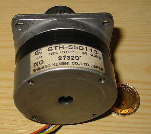
(The base voltage
of the motor is 4V)
The base voltage of the motor in the picture is 4V. According to the table the tuning voltage applicable if about 7-fold. Therefore the most suitable power supply voltage for this motos would be 28 V. For this purpose a 24V-transformer with rectifiers and with a filtering capacitor of minnimum 1000 uF/A would be suitable.
The maximum value of the power supply voltage is naturally 50V, this value must not be exceeded by all means.
The nominal value of the motor current is 0.95A. In case of H1 this should be adjusted by the potentiometer trimmer which is connected to the motor (see the description).
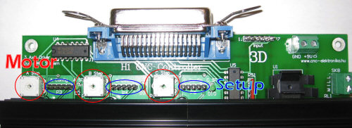
(Step and Holding currents setup)
Designing the current load:
When considering the current load of the power supply of the motor, the nominal
current values of the motors and the fact that our system is a half-step one
should be taken into account.
The safest design would be if the double of the nominal current value of each of
the motors were taken into account (because of the half-step system every other
step is performed by the excitation of 2 coils) and these were summerised. This
method would result very large current demand ( e.g. in case of 3 motors with 2A
the current demand would be 3 x 2 x 2 = 12 A, this would take in case of a
transformer of 30 V and a performance demand of 360 W). Fortunately this is not
necessary.
In the practice total synchron hardly ever occurs (or if this should happen it
takes place only for a very short time), and the duty cycle of currents is
continually varies because of the PWM-type regulation (it is only seldom 100%).
So the half of the value resulted in the above written method is suitable (in
the above written example 6A instead of 12 A). By doing so, it also will result
enough resources in the practice.
The little time till the total synchron should appear, can be supported by a capacitor of 1000uF/A or bigger.
It is important that the 2 voltages should come from independent transformers, or at least from independent coils of one transformer! The noise created by the motor should not get into the digital power supply voltage!
A tuning power supply has been developed for both H1 and Profi1 CNC controolers, which is ideal for small and mideium-size motors up to a performance of 150 VA, because 15 V or 30 V can be choosen by jumpers. The power supply contains all the necessary (independent) voltages, fault and noise protection.
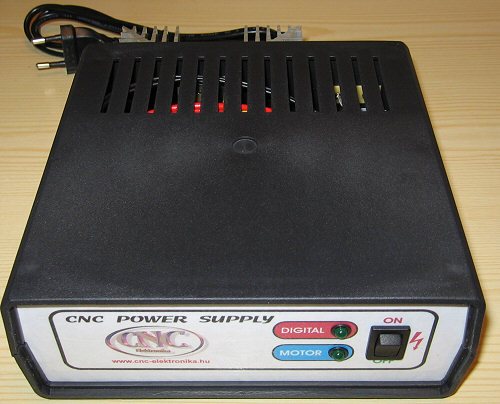
(Recommended Power Supply)

Specialities of H1 Tuning:
The excitation of the motors can be tuned during in operation too. The Step
potentiometer trimmer makes its effect only in the Chopper range (at lower rpm
values).
In the Chopper range both the motor and the controller have the highest warming
up (the current demand is the highest in this range). The warming up is the
highest at a motor standing, therefore the back-regulation by software (DSP) is
necessary. Because of this reason motors (and the FETs belonging to them)
turning at a high speed will have a less warming up than those of standing.
Summing up the above-written things it can be stated that the Step potentiometer trimmer determines the torque of the motor (its current demand and warming up) at lower RPM range, (in the Chopper range), it has nothing to do with increasing the speed, there is no use in trying to increase the speed by this way. The speed can ONLY be increased by raising the power supply voltage (strictly within the tuning factor!).
In the course of motor tuning care must be taken that an unstabilised motor power supply will drop a little its volatge with increasing current load. Therefore when the maximum speed of the CNC machine is determined gross load should be applied (e. g. by turning all the three motors at the same time). Determining the speed only by turning only one axis, its value will not be the true value in case of 3D movement, which may lead to shorts.
In the course of tuning care should be taken of warming up of the controller too. It should be checked during longer period of operation and the ventillation should be improved if necessary (e. g. by applying fans). It should not be forgotten that the highest warming up happens when the motors are standing or turning slowly.
The tuning of CNC begins with studying the resolution data of the machine
(mm/step) and the speed and acceleration is increased gradually from the lower
values to the higher values. If the speed of the PC applied makes it possible,
use always the Enhanced Pulsing option of Mach2 & Mach3 (stabilised Step
impulses). This is very useful.
In case of Mach3 the Sherline 1/2 Pulse mode should be switched off. This
increases the accuracy of the machine.
H1 controller has an Ultra Fast Delay power grade. This means that it
destroys the electric fields of the coils being switched off during the steps
very quickly. By doing so it speeds up destroying their magnetic fields (this is
a very important possibility to increase the speed of the motors). Because of
that working principle as high voltage increase as 100 V may be induced in the
coils of the motors during this time. Therefore take care of not touching the
wires of the motors, even if the power suplly voltage is only 12 V. These
energies warm up the FETs very much (the protecting supressor limits the voltage
to 100Vand dissipates the excessive energy).
The farther is the motor supply voltage downwards from the opening voltage level
of the supressor diodes (which is 100 V in case of H1), the more effective is
this Ultra Fast Delay mode. That is why it is better to use motors with lower
operating voltage (their inductivity is lower too). Because of the above-written
reasons the maximum allowed motor power supply voltage is 50 V.
This power grade has a side effect: because of the fix Fast Delay the PWM is
destroyed also very quickly, therefore the new excitation must be performed also
very quickly, which means a relative higher working frequency. The more frequent
cyclic magnetization causes a higher core loss in the motors, because of this
they warms up higher than motors driven by slow delay (bipolar) power grades. So
that the warming could be decreased, DSP reduces PWM frequency during holding in
position. As a result of that, the PWM voice becomes audible during holding in
position (about 2 kHz).
By applying this driving method substantially higher speed values can be
achieved than by using any kind of bipolar power grades.
![]() Using
two motors with one (common)axis:
Using
two motors with one (common)axis:
If it is necessary, two motors can as well drive one (common) axis. To do this, the motors should be totally uniform with 8 wires (universal motors).

(Using two motors with one axis)
The equivalent coils of the two motors should be in serial connected. The motors connected in the way presented in the figure will rotate in the same direction.
If rotation in a contrary direction is necessary, then (only) the two coil-ends belonging to one of the phases of motor No 1 (e. g. violet – green) must be interchanged.
From the viewpoint of design the resultant motor is a motor with nominal
current but with double voltage and double inductivity. According to that fact,
the maxmimum speed available will be lower than in the case of one motor would
be used. At least 30 V of motor power supply is recommended by all means.
This method is used first of all in case of foam cutting machines.
The H1 Controller supports using two motors with one (common) axis only in
serial connection! Parallel connection of the motors is not allowed, the reason
for that is the fact that the motors may get into oscillation at certain
resonance points and impulse losses and blocking may occure.
The reason for that phenomenon is that motors connected paralell fill each other
with energy during the oscillation and the current controll may collapse because
of that.