Hybrid/Native PWM Stepping Motor Control electronic Unit for Hobby CNC machines
Profi1
CNC Controller
Hybrid/Native
PWM Stepping Motor Control electronic Unit for Hobby CNC machines
![]()
![]() Discontinued!
Discontinued!![]()
Only
product support !
![]() Please
see New H1 CNC Controller!
Please
see New H1 CNC Controller!![]()
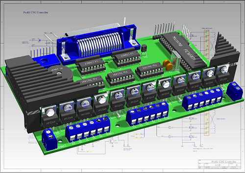
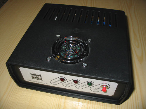
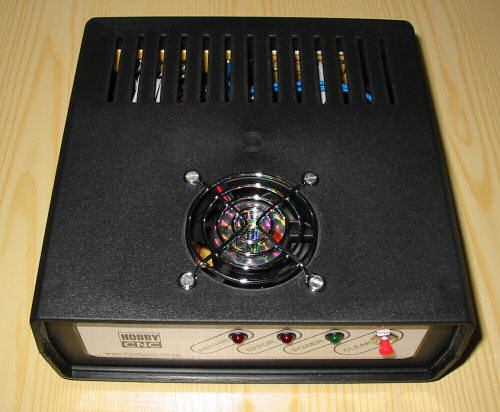
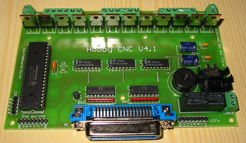
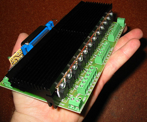
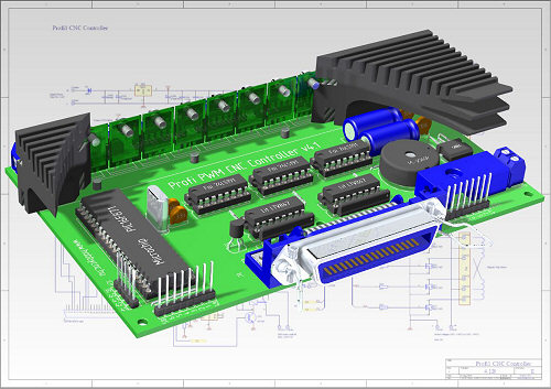
CNC Controller PCB V4.1B
Last modification: 11.05.2006
![]()
![]()
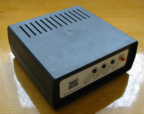
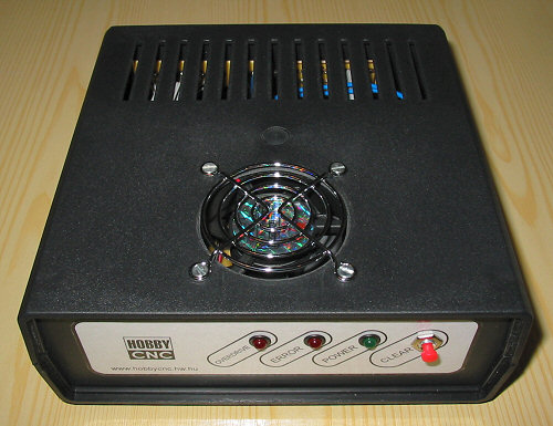
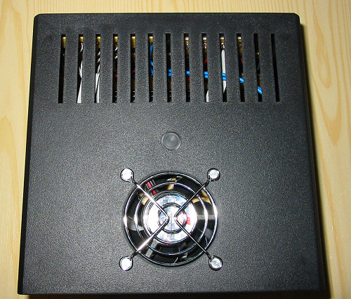
Box versions (Please Click!)
If load larger 8A
Possible Hobby CNC Axis combinations (with PWM CNC Controller and Mach2 CNC Software):
| CNC Number of Axis (Axis) |
PC LPT port
number (piece) |
PWM CNC Controller number (piece) |
PWM CNC Controller Tipe (2D or 3D) |
| 2 | 1 | 1 | 2D |
| 3 | 1 | 1 | 3D |
| 4 | 2 | 2 | 2D+2D |
| 4 special (ex. foam cut) | 1 | 1 | 2D+axis/2 motors |
| 5 | 2 | 2 | 3D+2D |
| 6 | 2 | 2 | 3D+3D |
Technical specifications:
- Standard, 3-axis
or 2-axis (3D or 2D),
Hybrid/Native PWM, Step/Dir-system CNC motor control.
- Unipolar motor drive, with 12 pieces of Logic Level MOSFET power
transistors (with integrated protecting supressor diodes).
- Possibility of mounting an external optional heat sink (for the FETs) (not
necessary if load does not exceed 2.5A/phase).
- Input voltage and power supply range of the motors: 8 ... 50 V or 8
... 90 V
- Maximum driving phase current of motors : 5A (above 2.5A heatsink is
necessary).
- Minirelay with potential-independent make contacts for controlling the turning
motor or the filament (maximum. ~250V, 5A).
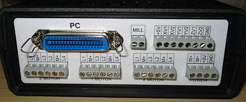
- PC interface: standard CETRONICS interface female for standard printer
cables (LPT port).
- Microcontroller: any 40-pin member of the PIC16F87x (16F871 ... 16F877) family
with 20MHz clock.
- Step/Dir signal detection (by the means of two-way counters).
- Full galvanic separation from the PC, by the means of opto-couplers.
- Built-in 5V supply (necessary input voltage: +8 ... +12V).
- Built-in ICP (In-Circuit Programing) interface, for uploading Firmware/Setup.
- PCB-integrated PIEZO speaker (for signal sounds)
- 3 pieces LED drive (Power supply, LED1, LED2) for combinated signals.
- 1 push-botton for obtaining signals and functions.
- Serial datalink (PC-Link). Direct Setup uploading (PWM) and extended
diagnostics.
Mechanical construction:

Large current FET's
Optional cooling space
- On board(160x100mm)-integrated
controller.
-7-point-fastener bore holes with a diameter of 3.5mm.
- Optional fastening of the heatsink to the PCB in 4 points.
- Stable, to the PCB soldered high-current terminals for the motors
(bolted joint).
- Line terminal for connecting end-positions, LEDs and push bottons.
- Partly SMD mounting.
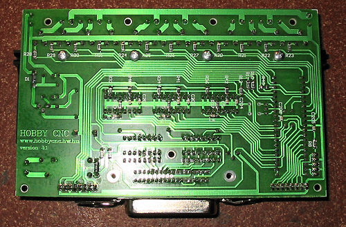
Partly SMD mounting
![]() Max.
5A and 90V!
Max.
5A and 90V!![]()


![]()
(zoom in click!)
![]()
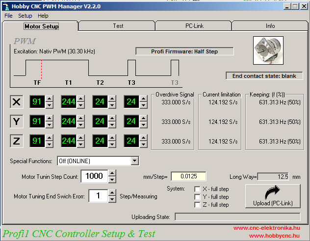
Profi Firmware (can
be ordered):![]()
Firmvare
V5.1.1 ![]()
Main features:
- 3-axis, independent,
Hibrid PWM (Pulse Width Modulation), motor control
(for unipolar motors)
- Independent, selectable 3 Step system (Half and Full Steps).
Select via PC-Link. Full step always two phase excitation.
(Half step = double CNC resolution without changing the hardware)
- 30 kHz clock, four-state (TF,T1,T2,T3), setup-adjusted, PWM
generator (wide range of field current control)
- 3-axis hardware Step/Dir detection (through the LPT port)
- 3D performance at a processing speed, greater than 13000 impulse/s
(simultaneous)
- Applicability of low-voltage (<8V), high-current motors (by the means
of PWM pulse narrowing)
- Applicability of motor control with elevated voltage (soft reset)
- maximum torque approximately by 20 % increased at low speed (T1)
- impulse loss detection (it can be ackowledged), and its smoothed
handling
- application of three-point digital filters (impulse filtering)
- smart end-position detection
- repeatable end-position detection (Power ON + push-button)
- motor overdrive detection and signalling (can be acknowledged)
- sound signals (Piezo)
- control card and motor diagnostics
- motor phase indentifying, end position, by the means of LEDs and
push-button test
- test of counters (X, Y, Z)
- automatic motor diagnostics (tuning) with programmable tolerance and
calibration path
- motor tuning and holding path PWM setup with a resolution of 3 times greater
- online diagnostics and forced impulse loss detection
- complex condition and error indication (via 2 LEDs + Piezo)
- all the functions and parameters are setup-adjusted by the means of a
Windows-based
program (by the means of direct PC-Link uploading)
- Direct possibility of accessing FETs (for each phase) (via PC-Link)
- Load test of the power supply of motors up to 200 % (PC-Link)
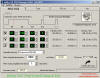
This Windows-based program can be used to access most easily to the very many
adjustments and functions programmed into the controller and to modify the
control parameters.
This program only used with Profi Firmware..
Please for the first time start PWM Manager, after entry
Controller in PC-Link mode (for uploading)!
Downloading possibility of the
software please see PWM Manager.
Uses PC Step/Dir CNC Controller Softwares (Not total list):
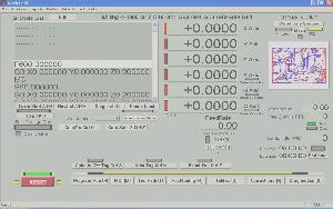
Recommended CNC Softwares: Mach2 CNC Controller!
| Ability Systems | Indexer LPT - software for CNC and robotic motion control. |
| Artisan-CNC Software | Artisan-CNC executes Fanuc-6 G-Codes, HPGL, or Excellon. It puts out synchronized TTL step & direction signals for up to 4 axes. |
| CNCLPT | CNCLPT Is A Full Function PC Based CNC Designed To Utilize Stepper Drives And Motors |
| CNCzeus | (new) CNC DOS controller |
| DAK's CNC | DAK's Turbo-CNC software |
| DANCAD3D | Welcome to www.DANCAD3D.com (sm) "Beta Test" Web site |
| DeskKAM | A Unique family of Windows based CNC products |
| Digital Design Technology | PLOTCAM routes step and direction signals through your computer's printer port to provide 3 axes of motion, contouring on the X and Y axes |
| Enhanced Machine Controller | Linux CNC |
| Kellyware | KCam 3 ROUTER/MILL CONTROL SOFTWARE for HOBBYISTS |
| Kevin Carrol | Stepster software |
| Larken LCAM | L-Cam is for controlling any type of 2 or 3 axis Milling machine, XYZ table or custom positioning table. |
| Luberth | Plotter / Engraver Qbasic / Quickbasic Controlled |
| Mark Whitis | Linux Stepper Motor Device Driver |
| Mach1/2 Master5 | Master5 is the most powerful and affordable way to control a stepper Motor from windows. |
| MAXNC | MAXNC DLX 4 AXES MOTION CONTROL SOFTWARE |
| Metalworking shareware | various |
| Microsystems | CNC Controller will drive up to 6 axises of motion simultaneously. |
| Practical CNC driver | CNC_D is a Windows 95 & 98 S/W product that provides control of a 4 axis-milling machine or lathe through the parallel printer port. |
| Progressive Logic | MyT'Mill for Windows Software - Powerful but simple to use! |
| Super tech | SuperCam imports HPGL plot files from AutoCAD and CorelDraw, then exports CNC G & M code files or directly controls of an XYZ table via the parallel port. |
| Yeager Automation | Control Your New or Rebuilt Machine With CNC Pro! |

(Mach2 CNC Controller Software)
Important:
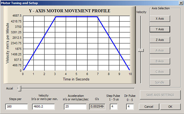
If use Mach2 CNC software, please setup Motor Tuning: Minimum Pulse Width: 10 uS, and Direction PreChange: 50 uS!

(Mach2 pulse datas)
If use Mach3 CNC software, please setup Motor Tuning: Step Pulse & Dir Pulse =4 or 5!
(Mach3 pulse datas)
Special
functions
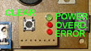
1. Functions available both in Online mode (PC - CNC mode) and via Setup procedure:
- Repeated
location of end-positions. It locates again the direction- and end position
assignments for the individual (X, Y, Z) axes.
Access: by depressed clear button turning on the CNC
(Power ON + push
button).
- Motor tuning. Determination of the gretaest speed (without step-loss) of the stepping motors
+ joined mechanical parts by the means of preprogrammed (Setup) step path and error
tolarence.
Access: by depressed YV1 and YV2 or ZV1 and
ZV2 end position switches turning ont the CNC
(Power ON + YV1 + YV2 3D)
or (Power ON + ZV1 + ZV2 2D).
- Holding path PWM tuning. Adjusting the force necessary to keep the motors in home
position by controlling the manual moving force at constant PWM frequency determined
during setup.
Access: By turned-on CNC press both end-position switches of the Y
or Z axis (Power ON + YV1 + YV2
3D) or (Power ON + ZV1 + ZV2
2D).
- Direct data-upload and extended diagnostics, through the LPT port (PC-Link).
Access: During Power On both end position switch of the X axis should be depressed (Power ON + XV1
and
XV2).![]()
2. Functions available only via setup:
- Identifying the motor phases by the means of end-position LEDs and push-button tests.
- Diagnostics of counters.
- Switching on the On line forced Inpulse Loss Detection (modified Online mode).
- Load test of the power supply of
motors up to 200 % ![]()
- Direct identifying of motor phases ![]()
- Elevated-voltage mode of motors
Detailed description of special functions can be found in the detailed description of the controller int he chapter of Manual Setup.
Documentation
(Free!)
(include in ordered
Controller CD)
|
3D (3
axis CNC) Controller: |
|
|
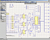
Schematics |
V4.1E |
|
External
connection diagram (3D) |
V4.1C |
|
Component list: |
V4.1C |
|
Schematic of the
power supply |
V1.A |
|
Windows PWM Manager |
Hobby CNC PWM Manager |
|
Mounting
prescriptions |
|
|
Simple LED Display |
Simple LED Display LED positions |
|
2D (2
Foam cutting)
version
modifications: |
|
|
Modification (2D kitt) |
|
|
External
connection diagram (2D) |
V4.1 |
|
Firmware |
By application of Special 2D Firmware |
![]() Components
dataseet:
Components
dataseet:
![]() Steping
Motors (Japan,
USA, GDR, etc.)
Steping
Motors (Japan,
USA, GDR, etc.)
![]() HALL-IC-sensors (Rafi)
HALL-IC-sensors (Rafi)
![]() 74LS191 (pdf 126 kB)
74LS191 (pdf 126 kB)
![]() LTV847 (pdf 117 kB)
LTV847 (pdf 117 kB)
![]() IRLZ24N FET (pdf 179 kB)
[normal voltage
version]
IRLZ24N FET (pdf 179 kB)
[normal voltage
version]
![]() IRL540N
FET (pdf 290 kB) [enhance voltage
version]
IRL540N
FET (pdf 290 kB) [enhance voltage
version]
PCB V4.1
To get a stabil and error-free operation some mounting prescriptions must be observed!
Supply voltages:
The negative terminal of the power supply of digital
circuits and that of the power supply of the motors (GND) can be strapped only
on the PCB. The supply current of the motors cannot flow through the
ground terminal (GND) of the power supply of the digital circuits!
The power supply of the motors and that of the Mill (milling motor, filament)
must be protected by fuses (Wickmann type) before the PCB!
The AC voltage for both the power supply for the stepping motors and that of for
the digital circuits must be provided by a safety transformer according
to the MSZ 172/1 standard!
(Info)
Power supply for the digital circuits:
The input voltage, that must be filtered by a capacitor of
minimum 1000 μF, can be between +8V és +12V. The maximum load of the digital
part is approximately 150 mA. This voltage must come from a transformer that is
independent from the transformer of the motor power supply, or at least from an
independent coil!
It is better to use lower input voltage, - about + 8 V, - as there is no need
int hat case for heat sink for the stabilizer IC of + 5V (above +12V it gets
warm, and its cooling may be necessary).
Power supplies for the motors:
Stabilization is not necessary but filtering by capacitors is a must. All the current load must be taken into account, and a capacity of 1000 µF should be encountered for a load of 1A.
Care must be taken that the unloadad motor-voltage should not exceed the maximum allowed voltage (50 V, or 90 V DC n case of elevated voltage version)!
Care should be taken of section and joints of feeding (because of high currents).
High-current wires should not be guided close to the contorller circuit.
Cooling of FETs :
Cooling is not necessary up to a load of maximum
2.5A/phase! If the load exceed this value, cooling is necessary.
As heat sink, aluminium plates fixed to FETs can be used or 2 pieces of special
heat sink with great heat-dissipation , which optionally can be ordered, can
also be applied.
All the FETs must be insulated from the heat sink!
The FETs must fixed by srews to the 2 pieces of heat sinks, which can be optionally ordered. Their insulation is necessary. The heat sink is fixed from the bottom of the PBC by plastic screws through the specially formed borings (4 pieces).
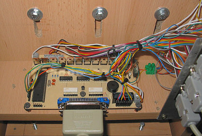
Mounting of the PCB:

Connections(V4.1)
|
|
|
|
place of end switch |
place of display |
(in-case-built-in)
The PCB must be mounted possibly through all the mounting bores. It is necessary to place insulating (e.g. made of plastic) underplates above the metal distance pieces, between the PCB and distance pieces! In the course of mounting the PCB should not be bent.
Int he course of tightening the bolt joints the move of terminals should be prevented (so that it could not be twisted)!
Putting the unit into operation:
Check if polarity of terminals of the power supplies (power supply for the digital circuits and for motors) is correct.
At first the PIC mustn’t be in its case, motors should not be connected, and power supply for the motors shoould be turned off (+8...50V or +8...90V)!
By these conditions and with the power supply for the digital circuits on, Vcc (+ 5V) and its polarity should be checked at the pins of PIC (see schematics!)
Following that turn on the power supply for the motors and check the value and polarity of the voltage between CON18 or CON 21 or CON27 or CON30 or CON33 positive and CON35 terminals.
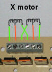
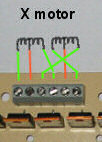
Then turn of f the motor supply and connect CON18, CON21, CON24, CON27, CON30, CON33 points to the coil tap terminals of the assigned (X, Y, Z) motors (they can be identified by a resistance instrument) according to the figure.
The correct phase-order necessary for the unidirectioal rotation must be searched!
There are two possibilities for that (recommended 1. method!):
1.
Place the preprogrammed PIC into its case.
Then connect the motors first in the following way:
Now turn on both power supplies and using the moving test function of PWM Manager programme check whether the rotation is correct (at low number of steps).
If incorrect stepping is noticed, exchange both ends of one of the coils e.g. as it is shown:
2. (alternative possibility):
Turn on the motors’ power supply (the coil tap terminals are under voltage, the other ends are free, - in the air)!
Contact one after the other the free ends of the phases to the negative terminal of the power supply of the motors (e.g. CON35) for a moment by using a piece of wire.
The motor will jump to the position assigned to the given phase. Note the direction and measure of the move.
Search for the correct phase order, with that you can get unidirectional rotation by using repeated touchments.
The actual direction does not count, only the fact that the motor should rotate in the same direction in each touchment!
Repeated toruchment order:
1--- (the motor makes a step forward)
-2-- (again a step forward)
--3- (...)
---4 (...)
1--- (again a step FORWARD!)
... (...)
If you could get the correct order, note it and connect the lines to the terminals (for each axis)!
1 -> CON17 (for the axis X)
2 -> CON19 (.".)
3 -> CON20 (.".)
4 -> CON22 (.".)
1 -> CON23 (for the axisY)
...
For further information see information of PC-Link.
Contact the end-positions (care should be taken not to exchange the axes), LEDs
(take care of the polarities) as well as the push button.
Take the PIC into its case, if you haven’t done that, (if it is empty yet, with the digital power supply on upload the Firmware on the ICP).
If everything is ready, it is worth performing all the tests (see knowlidge of the firmware).
In case of elevated motor voltages see description of Motor tuning.
If everything has been done, the controller is ready for operation.
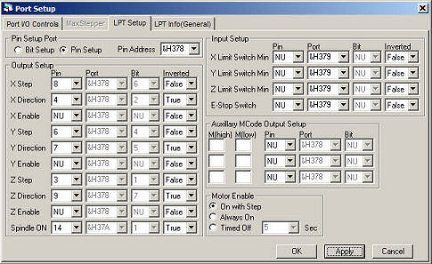
PC-side configuration of the controller (PCB V4.xx):
(KCAM4)
(Master5)
(Mach2 bit setup)
Please setup Motor Tuning Minimum Pulse Width:
10uS, and Direction PreChange: 50 uS!
![]() If
use Mach3, then Scherline mode=off!
If
use Mach3, then Scherline mode=off!![]()
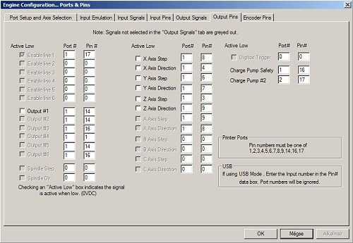
| Function | LPT port pinout |
| Port=&H378 | |
| X Step | 8 |
| X Dir | 4 |
| Y Step | 6 |
| Y Dir | 7 |
| Z Step | 3 |
| Z Dir | 9 |
| Port=&H37A | |
| Spindle(Mill) | 14 |
(PCB V4.1)