Usage of PWM Setup, Test and PC-Link
(FREE !)
![]() Hobby
CNC PWM Manager
Hobby
CNC PWM Manager![]()
Usage of PWM Setup, Test and PC-Link
(FREE !)
Modify: 02.22.2006
![]() Manager
update for Firmware V5.1.0
Manager
update for Firmware V5.1.0![]()
By this Windows-based program all the adjustments, special functions and tests of Hobby CNC Profi1 Controller can be accessed. The PWM Manager program is based upon entirely on the services of Firmware V5.x.x. By the means of the PC-Link mode all the Setup data can also be uploaded to the controller without the use of external PIC programmer. With the help of PC-Link further services can be accessed.
![]()
PC-Link is a hidden serial data transmission possibility using
the already built-in Step/Dir datalines. It does not use any further bits, so it
does not crash with any other CNC contrioller programme, but just because of
that the two modes (On-Line and PC-Link) cannot be used at the same time. In
order to change between the two modes, both end position switches of one of the
shafts (XV1 and XV2) must be kept depressed at the monent of starting the
controller (Power On). The controller indicates with a
series of sound signals and lighting both LEDs that it has entered into the
PC-Link mode. In PC-Link mode the PWM generator does not work and the phase
excitations of all the motors (FETs) are in switched off position.
PC-Link is a protocoll series with its own command set, by which data can be
directly uploaded to the Setup registers and the particular FETs (motor phases)
are directly available.
Please for the first time start PWM Manager, after entry Controller in PC-Link mode (for uploading)!
Hobby
CNC PWM Manager V2.1.x
(Full description)

(This is pictures old version V2.0.9!)
![]()
Installation:
The programme can be used under any type of Windows (Win9x-XP). After unpacking
Setup.exe must be started. As the programme has its own I/O driver, before running it first
the driver must be installed! Before the installation of the I/O driver �IO Driver Setup� (which is one of the programmes newly installed into the Start menu) must be started. This must be installed only once! After installing the driver Windows must be restarted. PWM Manager can only be used following this installation. I/O Driver is a product of Scientific Software Tools, Inc.
Programme Setup:
As there are bit acllocation differences between the PCB V3.2 and PCB V4.0
versions of the CNC controller, the PCB version of the programme must be
adjusted after starting the programme. This can be done in the Setup/Mode of
communication/PCB V xx menu.
After that the address of the LPT (printer) port communicating between the
controller and PC must be entered on the Test panel (in the LPT port
window). The addresses of LPT1, LPT2 and LPT3 come in a line from up to
downwards. The adjustments are stored by the programme.
Usage:
Menus:
File:
Setup Open. Opening a saved file containing Motor Setup Data. It is used mainly to serve PC-Link.
Setup Save. It is to save the data of the Motor Setup panel.
Exit. It is to exit from the programme.
Setup:
Holding path freqency. Connstant and variable can be choosen. It can be given whether the controller should try to keep the frequency determined by the sum-value constant during adjustment of T2 and T3, (by increasing T2 and decreasing T3 and vice versa).
Method of Communication. The PCB Version number of the controller�s PCB can be given here. It influences the bit allocation of LPT port.About:
Short introduction of the programme.
Panel:
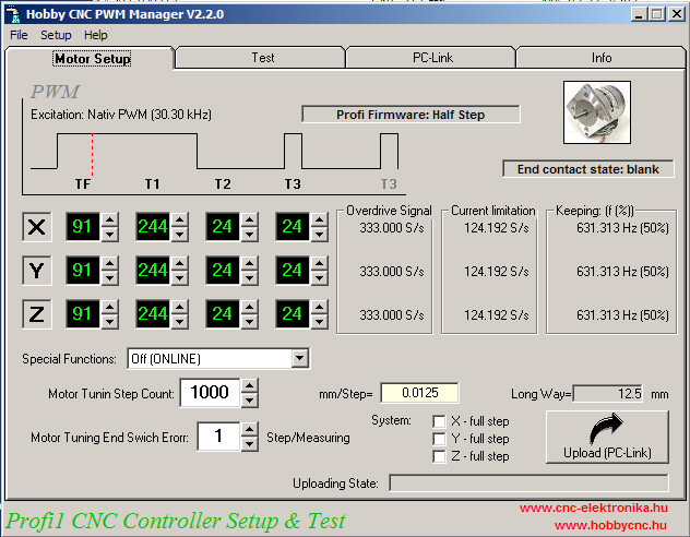
Motor Setup:
PWM Manager
All the Setup data of the controller can be entered on this
panel. The entered data can directly be uploaded to the controller by the means
of Upload (PC Link) button (in PC-Link mode).
All the timing values (black fields) are multiplication of time units (1/f)
derivated from the base frequency of PWM generator.
The most important Setup data and their
explanation:
(the yellow fields are necessary only for the calculations of the Manager
software)
TF and Overdrive indication fields:
They determine the threshold levels of overdrive indication of the motors. Their value is an initial value, which can be fine tuned by Motor tuning of the controller (see Special functions). It is the speed, that is used by the controller in the course of localization of the end positions. Its value is correct when it means the biggest speed allowing the direction change without any steploss. It is worth having it determined by the diagnostic routines of the controller. During Setup we can give only an initial value, the diagnostic routines will increase the speed starting from this value. The initial value must not be too large. S/s=Step/sec.
T1 and Max Nm Fields :
They determine the lower speed point of the in position holding PWM (holding path) mode, which is the speed value belonging to the biggest torque point at the same time. At this point the motors are the hottest. Motors with excitation time greater than this value will be in position holding state exceeding this time(based on T1 and T2). Their torque and warming cannot unlimitedly increased. S/s=Step/sec.
For the exact determination of their value see the description of Motor Tuning.
T2, T3 and Holding Path (f(%)) fields:
PWM time of holding path, frequency, and duty cycles (%). T2 is the pause time of PWM excitation, T3 is the excitation time. Their summarised value determines the Holding Path PWM frequency. The Holding Path torque and the extent of cooling can be controlled by that.
Special Functions Window:
The special function intented to be activated can be choosen. The possibilities available depend on the category of Firmware too.
Step-number of the Motor tuning path, mm/Step and Path length fields:
The step-number belonging to the Special functions/Motor tuning, the move(ment)/step in mm and the resulted path length can be given (can be read out). This value is valid for all the three axes! The bigger the step-number, the more accurate the measurement, but the longer is the process.
Motor tuning end position error tolerance window:
It is the value for the compensation of uncertainity of the end position belonging to the Special function/Motor tuning. In the course of measurement, the controller does not consider the step-loss during that to the step error of the motor (eliminating the uncertainty of the kip point of the end position sensor).
System windows:
Selectable independent motor step system (default=half step). If full setep selected, then always two phase excitation in steps. Half steps= double resulution.
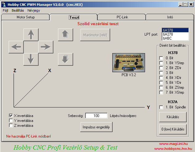
Test:
Simple move and bit tests (Hungarian version)
In the On-Line mode of the controller it is also possible to
test the controller card without any other CNC controller software. It contains
a reliable pulse generator, therefore it can be used first of all for diagnostic
purposes.
The moving direction buttons are active only enabling the pulse generator.
By direct bit-setup the bits of LPT port can be accessed.
By X, Y, Z invering the movement directions can be inverted.
The active bit allocation mode can be found under the photo of the controller
PC-Link:
PC-Link (Hungarian version)
The FETs, and so the phases of the motors can be directly
accessed. The functionability of each FET can be checked by that, and the
correct phase sequence belonging to the uniform rotation direction of the motors
can determined with its help. The excitation of motors takes place by integer
steps (excitation for phases), so the incorrect phase sequence (line
arrangament) can be better detected. The excitation switched on is of full DC
characteristic (there is no PWM),.therefore its use for a longer period is not
suggested (strong warming-up of the motors).
By the Step buttons an integer number cyclic stepping is performed (as in case
of making contact by hand).
By the Load test of the Power Supply the load capacity of the power supplies of
the motors can be checked (voltage break-down and the protection if it is
built-in!). The power supplies can be loaded gradually (step by step) by using
the motors from 0 to 100 %, and after loosing the two-grade limitation even up
to 200 % of the nominal value. Load exceeding 100 % needs careful attention, do
not apply for longer periods.
By pressing the STOP button, the load can be cancelled at any time.
Additional topic: Motor tuning at elevated voltages
![]()
![]() PWM
Manager V2.2.0 English (zip, 4.4 MB)
PWM
Manager V2.2.0 English (zip, 4.4 MB)![]()
Only for Firmware V5.1.x
PWM
Manager V2.1.1 English
(zip, 4.4 MB)
Old Firmware (V5.0.3 and minor)
![]()
In case of upgrade the old programme must be removed first (uninstall).
Sample Set-up:
(just to begin with)
|
Explanation |
Sv pont
Breakpoint |
Overdrive
Indication Threshold |
Hold-Path
Holding Force |
Hold-Path
Frequency |
Special functions: |
File |
|
1* |
124 |
333 |
50 |
631 |
Switched off |
|
|
2* |
606 |
606 |
50 |
631 |
Switched Off |
|
|
3* |
1010.1 |
1010.1 |
50 |
631 |
Switched off |
|
|
4* |
124 |
333 |
25 |
631 |
Switched off |
|
| 5* | 2020 | 1010 | 58 | 631 |
Switched off |
2.2V.pwm |
| 6* | 378.787 | 606 | 45.8 | 631 | Switched off | 23LMC701_01.pwm |
Explanation:
1* Base Set-up. The preprogrammed PIC is uploaded with
these data.
2* Japanese 5V motors operated with a power supply of 12V. Suggested initial
value, see its tuning in the chapter of
Motor tuning!
3* Japanese 3V motors operated with a power supply of 12V. Suggested initial
value, see its tuning in the chapter of
Motor tuning!
4* Suggested values for GDR (SPA 52/60) motors, operated at nominal voltage (for
example. A motor of 12V operated with a power supply of 12V).
5* Japanese 2.2V motors operated with a power supply of 12V. Suggested initial
value, see its tuning in the chapter of
Motor tuning!
6* Minebea 23LM-C701-01 or Japan Servo KP56QM2-001
motors operated with a power supply of 12V.
Suggested initial value, see its tuning in the chapter of
Motor tuning!
Known errors:
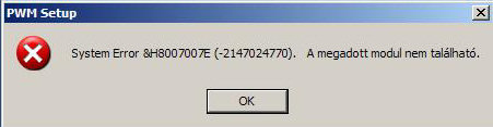
Solution:
MS Office XP must be installed :-(