Fine Tuning of Stepping Motors to Maximal Performance by the Means of Profi1 Hobby CNC Controller
![]()
Fine Tuning of Stepping
Motors to Maximal Performance by the Means of Profi1
Hobby CNC Controller
Modify: 04.17.2005
As the impedance of the motors applied is a given value and the brake resistance of the driven mechanics can not be changed either, increasing the speed (performance) can only be made by increasing the supplying voltage of the motors. The current flowing through the coils of the motors also affects the torque, care must be taken so that the nominal currents of the motor in the high step-number speed-range could be reached as soon as possible.
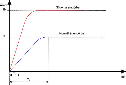
(Consequences of voltage raising)
Ia = current value at the nominal voltage of the motor (at
speed of 0).
Ib = current value at increased voltage of the motor(at speed of 0 ).
Ta = time necessary to reach the maximal current at nominal motor voltage.
Tb = time necesary to reach the maximal current at increased motor voltage.
Növelt áramgörbe = current value at
increased voltage
Normál áramgörbe = current value at the nominal voltage
Idő = Time
Tb < Ta
If the motors are operated not at their nominal voltage but at an elevated value (according to my experiences at a value of 2 - 3 times higher that the nominal value) they can have a much larger torque because of the bigger slope of current curve at large impedance belonging to higher revolution.
Reducing the speed of the motors, results in a proportional reduction of inductive reactance of the coils. The current intensity obtained is increasing in reciprocal ration to that. Operating motors over their nominal current intensities for longer period is of course not allowed.
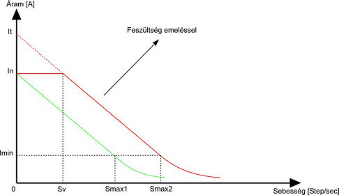
(Increasing
the speed by voltage increasing )
Current-speed curve at nominal
voltage.
Current-speed curve at elevated voltage.
In = nominal coil-current of the motor.
Imin = minimal current (torque) necessary for moving the mechanical parts,
theoretical value.
It = unlimited current intensity at zero speed belonging to the elevated
voltage.
Smax1 = maximum speed that can be reached at the nominal voltage.
Smax2 = maximum speed that can be reached at elevated voltage.
Sv = current-control breakpoint (limitation to the nominal current),
Feszültség emeléssel = elevated voltage.
Áram = current.
Sebesség = speed.
Smax2 > Smax1
Sv pont is the speed (stepping time) where the motor , - at a given value of the elevated voltage, - takes up exactly the nominal current for its each coil. If a value downward from that speed were applied, - in other words more time were allowed between the steps, - the current would exceed the nominal value applying to the coils. That must be avoided by proper adjustment of the controller (Setup). In case of lower speed values than Sv (in other words exceeding the longer stepping time), the controller must switch into a so-called resting (in-position holding) current-control after reaching the nominal value of the current. The current of the coils does not exceed the nominal value, the device even spends more and more time in resting mode as the speed if reduced. In this way overheating of the motors can be avoided.
Point Sv can be adjusted by the means of the T1 registers of the controller (for X, Y, Z axes).
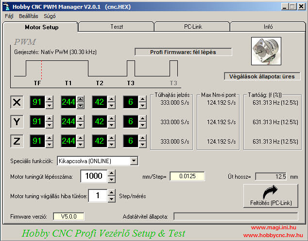
(Please download
English version! Current-control
data)
Sv = 1/(T1*PWM oscillator base)
Where the PWM oscillator base is depending on the firmware applied (10 kHz or
30.30 kHz) 0.0001 (Hobby), 0.000033 (Profi).
The value of Sv point can be directly read in the field of Max Nm - ri point
[Step/sec]. Beside that this is the speed value of the motor where it can give
the maximal torque with taking up the nominal current.
Registers for each axis:
T1 - time of the stepping field current.
T2 - break time of the hold-on branch current.
T3 - time of the hold-on branch field current.
Hold-on branch current = field current holding the motor in standing position
(PWM).
![]() Choosing
power supply:
Choosing
power supply:![]()
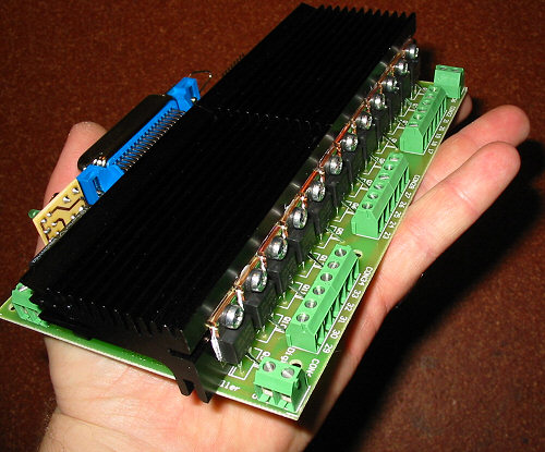
(Elevated voltage version, max 90Vpower supply for
motors)
Experiences show that if elevated performance is necessary,
the power supply should be 2-3 times higher than the nominal motor voltage. The
maximum value of the controller must not excced that value (50V or in the case
of the elevated voltage version 90V)!
The bigger the inductance of the motor is, the more reasonable it is to increase
the voltage. Of course this bigger inductance produces higher inductive surge,
which must be dissipated by the supressor protective diodes of the FETs (higher
electric stress). As the supressor diodes work above 55V or 100 V depending on
the verison, the motor voltage choosen must be lower than this value. The
inductive surge arising during stepping will be added to the motor power supply
and when the spuressor diodes begin to work (dissipation), this will affect as a
motor-brake, which causes performance deterioration (maybe the gain that can be
reached by increasing the voltage vill be lost by the brake-effect made by the
supressor diodes).
According to my experiences if a switching power supply or a stabilised one is choosen, the inductive spikes of the motors may disturb the electronics of the power supply, therefore if possible the traditional (transformer, -diodes-capacitors) power supply should be preferred, or the effect may be reduced using stronger smoothing or by the means of the Dump circuit.
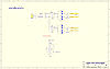
(Circuit
diagram of the power supply)

Recommended PWM insensible tuning power supply (12/24V;
120VA)
The output voltage depends on the load: 15/30V.
Of course there is no unlimited increase of the motor performance can be reached in that way, because the the available performance is also limited by other parameters depending on the construction of the motors.
![]() Determination
of Sv pont (T1):
Determination
of Sv pont (T1):![]()
![]()
For the determination of the control breakpoint (Sv) the continuous measurement of the current of the particular motor is necessary, so a suitable fast ammeter is needed and it must be seriel-connected with the clamped moving contact termination of the motor examined, so that the current of each phase could be measured at the same place. The other possibility is to seriel contact the meter at the power supply, but in that case the other motors must be disconnected or switched off, so that they could not disturb the measurement. As the current to be measured is impulse-like, using a normal ammeter no accurate measurements (only averaged ones) can be made because of its inertance. For the most accurate measurements a cathode-ray oscilloscope would be needed so that current peaks also could be measured.
The main points are the followings:
- Measurement:
In the full range of the motos-speed (0-100%), the current being taken-up must
be continuously checked by measuring. At different speed the motor takes up
different current (it depends on the rev and on the PWM excitation of the
controller because of the varying inductances). The value of the current should
never exceed the value of the nominal current! In case there is a rev (speed) at
that it exceeds the nominal value, by reducing T1 the maximum value of the
current taken up must be lowered. If the current does not reach the nominal
value in the full range, T1 should be increased until the current reaches
somewhere in the revolution range (usually in its lower thirdpart) the nominal
value.
In case of measurement performed with ammeters it can be reached this value even
at lower values (because of the inertance of the device). Applying Profi
Firmware one or two coils will be excited because of the half-step control,
therefore In (nominal current), or double of that will be taken up.
The inertance of the device and the variation of In or of the double
of that will approximately compensate one another, therefore if simply In
is aimed to be reached, you wont be mistaken.
- Observations:
For fine-tuning of the motors the control program Mach2 CNC is suitable
very much because its uniform stepping pulses. Mach2 must be so adjusted
that the motor could only slowly accelerate for high speed (that it can
tolerate), and the value of Jog must be adjusted at least to 700 mm by the means
of the movement controlling push buttons, after that you should click to the
movement controlling pudh button of the particular axis (programmed motion). In
this condition the controller accelerates the motor at the acceleration you have
adjusted up to the maximum speed, and then before it would reach a motion of 700
mm, it will slow down the motor and stop it. In the meantime you can measure the
current and you can observe the motor running in wide range of rev.
As our measurement is not very accurate and the motors have different properties
based upon the revs and current values, a very important test should be
performed yet.
If the motion of the motor is jerky at any speed (it skips), a typical hum can
be heard and the current taken up is incresed, it means that its iron is
overexcited. In this situation T1 should be lowered a bit and the running-up
must be tested again. It is worth performing the test so that the motor is
loaded in its position, or braking it fine with our hand. A motor running free
can produce false tests (in case of jerk)! By lowering T1 the excitation of the
motor is reduced under the saturation point of the iron until it smoothly runs.
T1 should not be reduced in an excessive extent, because in that case the torque
of the motor would also reduce at lower revs.
If the motor motion is jerky a bit directly after the start, it means that the
force holding in position is not sufficient. In such a case the ration of T2/T3
should be increased (lowering T2, or increasing T3). It is essential that the
braking torque should keep the motor in position with siutable stability,
because in case of a sudden start the motor may skip back-and-forth for a moment
if the holdon branch current is weak. It is particularly applies to the high
resolution (pl: 1.8°-os) Japan-made motors. The hold-on branch current should
not be too high either so that its „resting” characteritic could make its
effect.

Resonancia
point of maximal current pont (wmv video, 594 kB)
This video one 1Nm motor (3.6V, 3A)
from 12V power run.
- Limits:
If the motor voltage is raised out of measure, the current increases with a
great slope and reaches its nominal value sooner than the motor could have
suitable torque. If in such a case the current is also limited to its nominal
value by T1, the motor will not have enough time to reach suitable torque.
Thus if the voltage exceeds a particular level, the torque of the motor will
begin to reduce again. Therefore the motor torque cannot be elevated
indefinitely by voltage-increasing.
If the controller is prpoperly adjusted, it dos not allow the motor to take up a current value higher than In (the nominal one) and utilize well the resources produced by the elevated voltage.
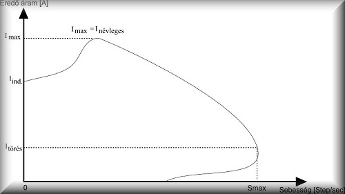
(Resultant
current curve of stepping motors)
Iind=initial
current (PWM controlled)
Imax=PWM-->DC switching point (T1: under that PWM control, above that
pure DC drive)
Itörés=break-down point, it is the maximum speed value at the same
time
Eredő áram = main current
Sebesség = speed
Inévleges = nominal current