(fine tuning)
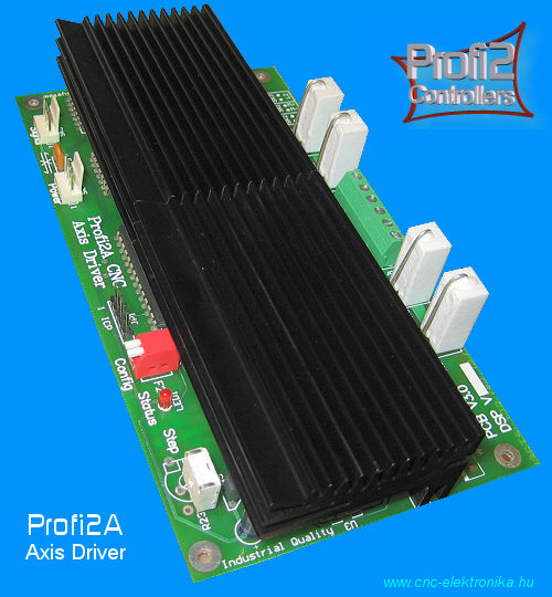
![]() Tuning
of Profi2A CNC Motor Controller
Tuning
of Profi2A CNC Motor Controller![]()
(fine
tuning)
Modified: 2007. február 25. vasárnap
The information published here is not necessary to run Profi2A controller. The controller has an Easy Setup (there are preadjusted parameters and only one potentiometer trimmer is to be adjusted to the current of the motor), but if one would like to know what happens and would like reach the maxmimum power of the controller or would like to know the details, the following may be useful.
![]() Theory
and limits:
Theory
and limits:
Profi2A CNC stepping motor controller has a current
regulation based upon the Chopper principle, which uses a 20 kHz PWM geneator
adjustable in three stages in the holding path during stepping. The current
limiting electronics tunes the duty cycle of the PWM (there are two independent
chopper circuits for each motor). The kipping points of the chopper circuits are
determined by a DSP algorithm with the help of a reference voltage generator in
the function of the current, phase position and time. The regulation is for
constant motor power. So the power and the moment of the motor is constant as
long as the controller is able to obtain the necessary voltage from the power
supply.
The moment provided by the motor is proportional to the consumed electric power,
therefore the stable and constant power consumption should be aimed. If the
power consumed decreases, then the moment of the motor will decrease too, if the
power consumption iscreases, then the motor overheats as the time goes (it may
burn off).
The primary reason for the fall of the moment is the inductivity of the coils of the motor. The additional electric resistance created by the inductivity, (which reduces the current consumption and by that the power consumption) depends on the frequency and so on the speed. The greater is the speed (stepping number) a stepping motor is driven by, the greater the voltage it needs to provide the same moment. In other words, the voltage applied to the motor should be steadily increased if constant moment is aimed.
The controller performs this voltage increasment by measuring and in a
stabilised way. It is able to perform the stabilisation until the voltage
demanded by the motor equals to the power supply applied to the motor. In case
of further speed increasement the controller is no longer able to stabilise the
power of the motor and its moment begins to decrease. This is the kipping point
of the control.
Under the kipping point (at slower speed) the controller works in chopper mode
(with a stabilised moment), above that point the controller works in DC mode
(with decreasing moment).

(Motor voltage request for speed)
As large chopper range as possible should be aimed, because the moment of the motor can be maximized only in this range.
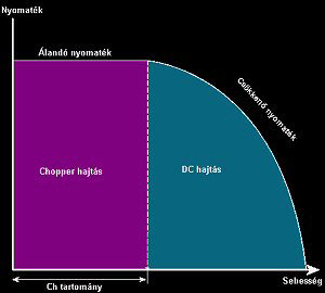
(torque graph)
The stepping motors can be used in DC range too, but their moment quickly
falls with increasing the speed.
The chopper mode can only be extended by raising of the voltage (the power
supply) applied to the motor. In case of a motor coming to standstill (the speed
is 0!) the controller must be able to controll the current to the resistance of
the motor (which is only a few Ohms).
The tuning factor show the regulation range the controller is capable to
control. It shows how much voltage the controller is able to regulate in case of
a given motor. If a voltage value greater than this is applied to the motor,
then the controller cannot regulate it, and the motor will overheat. Profi2A
Controller has an approximately maximum 25-fold tuning factor.

![]() Designing
of the Power Supply of the Motor:
Designing
of the Power Supply of the Motor:
Calculation of the voltage:
The tuning factor is a multiplier factor depending on the inductivity of the
motor. In case of P2A the greater the inductivity of
the motor is, the smaller the tuning factor is.
The controller switches off and on the coils of the motor, so that the current
could be held at its nominal value. This switching off and on produces very high
inductive voltages. The FETs of the power stage are protected by their
integrated supressor diodes (they lead away the induced voltage). The voltage
supression produces considerable heat. The greater the inductivity of a motor
is, the higher the heat is, which is produced by the supression. This heat warms
the heat sink of the controller, therefore the smaller the inductivity of a
motor is, the higher the voltage ratio (tuning) it is able to tolerate. The
tuning factor is the ratio of the power supply voltage and base voltage of the
motor (T=Upower supply / Umotor ). The use of motors with
small inductivity is advantageous, though the situation can be improved by
connecting the coils in parallel (e. g. in case of 8-wire motors).
As most cases there is no data on the inductivity of the motor and it cannot be measured, from the Ohmic coilresistance conclusion can be drawn to its internal inductivity (it is far from being a perfect method, but it can be applied). According to the conclusion, the greater the Ohmic resistance of the coil is, the greater its inductivity can be (high resistance means thin wire and a lot of winding and as a consequence greater inductivity).
The following table gives practical information on the relation between the base voltage of the motors and the maximum suggested power supply voltage:
|
Base voltage of the motor: |
Recommended power supply voltage: |
|
1V |
25V |
|
2V |
40V |
|
3V |
50V |
|
4V |
60V |
|
5V |
70V |
|
6V |
70V |
|
8V |
80V |
|
9V |
65V |
|
10V |
50V |
|
11V |
40V |
|
12V |
30V |
|
etc. |
... |
(Motor Power Voltage select table)
![]() Warning!
Above
50V increased care must be taken of the device!
Adherence of prescriptions of the electric shock protection is compulsory
(dangerous voltage)!
Warning!
Above
50V increased care must be taken of the device!
Adherence of prescriptions of the electric shock protection is compulsory
(dangerous voltage)!
An example:
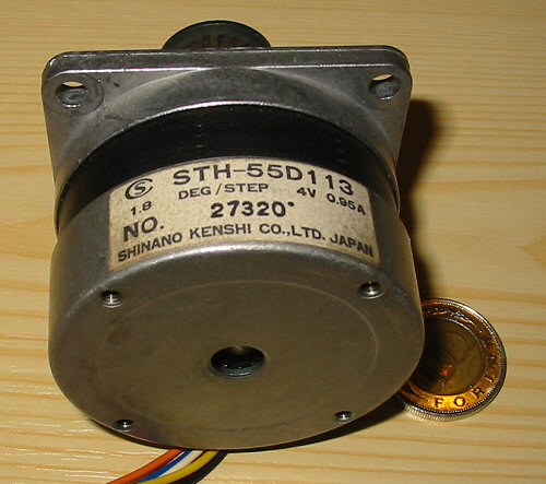
(Stepper motor)
The base voltage of the motor that can be seen in the picture is 4 V. According to this fact, the maxmimum tuning voltage is about 60V. Therefore the most suitable power supply for this device would be a power supply providing 60 V voltage. Applying a transformer of 42 V, after rectifying and filtering (1000 uF per 1A current) a DC voltage of approximately 60 V can be obtained.
The maxmimum allowed power supply voltage is 90 V. This value must not be exceeded by all means!
The nominal current of the motor is 0.95A. Applying P2A, this value must be adjusted by the potentiometer trimmer the motor is connected to (A, B, C or D on the card, see the description!).
Designing of the current load:
When designing the current load of the power supply, the nominal current of the
motors and the fact that our system is a half-step system must be taken into
account.
Based upon the the worst case, the double of the nominal current of each motor
would be taken (because of the half-step system every other stepping happens by
the excitation of 2 coils) and these should be summed up. By doing so it would
result in very high current values ( e. g. in case of 3 motors with 2A nominal
current consumption, the current demand would be 3x2x2 = 12 A, at a voltage of
30 V this results in a power of 360 W, and a transformer of 360 W). This is
unnecessary!
In the practice this perfect synchronous drive hardly ever occurs (or if it
occurs, it will exist for a very little time) and because of the PWM regulation
the duty cycle of the current varies continuously (it is hardly ever 100 %).
Normally the half of the above obtained current demand can be taken (it is 6A in
the above-written example). In the practice by doing so the device will have
enough reserve resources.
This little time during the perfect synchronous drive would exist can be covered by the energy stored in an enough high capacitor ( minimum value is 1000uF per 1A) without any problem.
![]() Adjustments
and usage:
Adjustments
and usage:
Step excitation:
The nominal current value of the motor must be adjusted by the STEP (R23)
potentiometer trimmer. The potentiometer trimmer should be turned gently to
clockwise direction by the means of a suitable size of screw driver and its end
position should be observed. In this position the controller regulates about to
0.2 A.
Then turn the potentiometer to counterclockwise direction and observe this end
position too. At this point the controller would regulate to 8 A.
Then taking the turnable angle range, the
position providing the current our motor needs must be estimated and the
potentiometer must be adjusted into this position.

(Adjustment of Step excitation by the means of the Step
potentiometer trimmer)
The controller is not sensitive to the exact adjustment. The position can be
modified by adjusting the potentiometer trimmer at any time during operation.
If the CNC controller programme (e. g. Mach3) is adjusted to a relative low
speed (e. g. 500-1000 step/sec), and the motor is continuously driven by the
programme, by gently adjustment of the potentiometer trimmer you can hear how
the voice of the motor changes. According to the experiences the voice of the
motor clears up and the motor relatively calms down at the correct value.
Adjusting the potentiometer to this point, the motor runs smoothly without extra
hum and resonance even at high speed.
Application of 8-wire (univeral type) motors:
Each of the high power motors can be found here is this type.
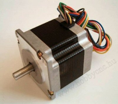
The highest power can be gained from an 8-wire stepping motor by the so-called parallel connection. The moment indicated among their specification always applies to that kind of connection.
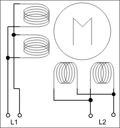
(recommended wires for universal step motor)
Always that kind of connection must be used. In this case the current to be adjusted is the double of the coil-current. Both the coil current and the phase-current values are often indicated on the motor. In case of parallel connection the phase current value must be adjusted.
Usage of the holding-path excitation:
After stepping and a dinamic stabilisation the controller reduces the excitation and the PWM frequency in the extent determined by the Setup (DIP switch). This is the holding path stage.
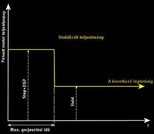
(Holding exitation)
By using this method the warming up of the motors otherwise standing can be further reduced. However you must know if the power supply voltage is increased this resumption possibility will be the first that you will lost.
The holding-path excitation is necessary because of holding in fixed position. The controller must be able to hold the motors even in a half-step position.
The suitable excitation is the smallest possible excitation, which can even
hold the motor in position (even in a half-step position). The force holding the
motor in position can be checked by hand if you hold of the end of the shaft in
case of a standing motor (but being on) and try to move it. The motor must
produce a definit, but not too large force against the movement.
For the most effective rest of the motor the frequency of the exciting current
is also reduced (so that the core loss proportional to the frequency could be
decreased). This happens by the modification of the PWM frequency, which results
in an audible voice in the motors. This is absolutely normal, the advantage is
the better cooling efficiency.
Overload Protection:
It protects the power bridge against overheating. At about 75°C it prohibits
the motors. The temperature of the heat sink is continuelly monitored by the
central MCU with the help of a temperature sensor. At a preprogrammed limit
value the MCU suppresses the power tarnsmission FET bridge (the motor switches
off).
Its running is indicated by fast blinking of the STATUS LED. In this case the
controller must be switched off and cannot be restarted until the bridge cools
down. Of course it means production of defective work when this happens,
therefore care must be taken to provide the possible best ventillation when
designing the cooling system (so that the cooling does not have to activate
itself).
Over 4A/phase current consumption the use of intensive forced cooling is
suggested.
Software:
The application of the Mach CNC softwares is definitely recommended. These programmes provide the smoothest stepping control, whose quality determines basically the speed can be reached by our system.
When using Mach2 and Mach3 softwares, the switching on the option "Enhanced Pulsing" is suggested.

(Switching on the option Enhanced Pulsing in Mach3
softwares)
This option improves further the smoothness of the stepping pulses, but it needs a PC of minimum 1Ghz to run.
Because of the pulse memory applied this controller is not at all sensitive to the pulse timing of Mach softwares.
(Mach3 pulse timings)
For the sake of safety both pulse data should be adjusted for 2.
It is even not sensitive whether Sherline mode is activated or not. It runs
perfectly in both modes.
In case of the use of very long ( >5 m) LPT cable, the switching on the Sherline
mode (because of the possible signal attenuation of the cable) is suggested.
![]() Speed
tuning of CNC machines:
Speed
tuning of CNC machines:
In case of a new or rebuilt machine, both the controller (Profi2) and the
control programme (Mach3) must be conformed (tuned to work together)
After the allocation of the communication ports (bits) of Mach3 (see the
description of Profi2B) the measurement unit (mm) and the calculated resolutions
must be adjusted first (any speed adjustment can only be performed after having
known these values). It must not be forgotten to store these data separately for
each axis (see the description of Mach3).
After that, the maximum speed of each axis must be searched. The search should be performed proceeding from the lower values to the higher values, with relatively slow acceleration. During the tests the axes are manually driven (controllling by the means of the keyboard) and their movement must be observed. The speed is gradually increased and the point at the motor comes to stand (it is shrilling but no longer rotating) must be observed.
It is necessary to know the moment curve of a stepping motor system for the proper tuning of the stepping motors and for understanding the behavior of our system. It is not themselves the figures what is important, but the relations among the figures.

(Complex CNC System torque graphic)
In this figure the common moment curve of an axis of a CNC machine, a stepping motor and Profi2A CNC controller can be seen.
Caption to the figure:
- "Mechanikai fékező nyomaték" = the braking resistance of the axis in
the function of speed,
- "Megindítás" = The minimum moment necessary to start the mechanical parts,
- "Léptetőmotor nyomatéka" = resultant common moment of the motor and
controller,
- "Chopper tartomány" = the range where the controller holds the motor at a
constant moment,
- "DC tartomány" = the range where the works as a synchronised motor with a
continually decreasing moment,
- "Max. sebesség" = intersection of the loading and driving moment, this is the
greatest machine speed that can be reached,
- "Billenési pont" = its position is determined by the power supply voltage of
the motor. It can be shifted (raised) along thecoordinate-axis of the speed
according to the extent of the tuning factor,
- "Max. start sebesség" – above that value the motor does not work in pulse mode
without acceleration.
From the figure it can be seen, that the usage of the acceleration is
extremely important, because the curve is a reclinate curve and the motor is
able to take up the revolution at once without acceleration only in a narrow
speed range. By the means of suitable acceleration the full curve can be
utilized.
It must not be forgotten that every harsh running (see
KCam4) equals to an abrupt start-stop, i. e. motor start without
acceleration. Because of this fact, stepping motors can utilize only the 0 –
max. start speed range by using KCam4. The situation is the same when the
acceleration is adjusted to its maxmimum value in Mach3 (Accel).
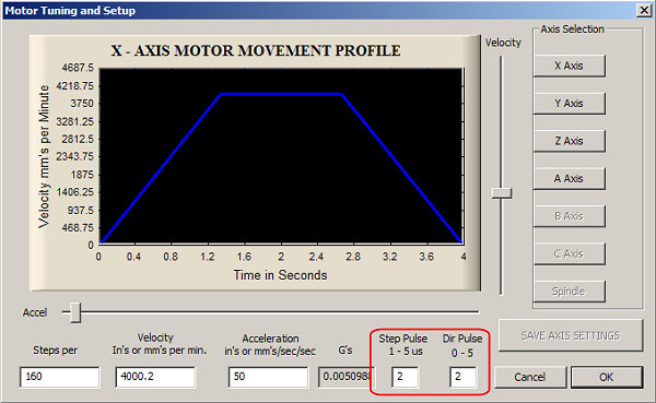
(Motor tuning screen of Mach3)
Recommended pulse values: Step Pulse=2, Dir Pulse=2.
In case of the foam cutting machines slow acceleration cannot be used (because of the technology of the process), but even in their case a minimal acceleration must be applied if they want to use the motors effectively.
The exact timing of the Step pulses provided by the PC is responsible for the balanced running. In case of Mach2 and Mach3 these are provided by the means of the mother board timers by the CPU, which means high stability (contrary to the timing based upon clearly the software, such as in case of Kcam4). As the Step signal is generated using the CPU, its load may influence its smotthness. Possibly do not run programmes with high resource need during moving the CNC. The smoothnes of the Step signal can be further increased by switching on "Enhanced Pulsening" – increasing the load of the CPU a bit (it is worth doing). In order to achieve suitable tuning, the minimal CPU speed prescribed by the manufacturers must be available, as Mach3 itself gives resource demanding tasks to the CPU too. The Window OS runs a lot of tasks in the background, these also must be taken into account (ideas for optimalisation can be found on the WEB page http://www.machsupport.com/artsoft/support/support.htm ).
From the moment curve it can be obtained that in case of a properly designed motor the maximum available speed is always in the DC range. The motor is properly used if the coming to stand because of the loading moment is not much before the blockage of the motor running without any load (it is very good if it is above 75 % ).
It is important to know that in DC range there is no steploss (despite that the moment is falling). If the stepping fell out of synchrone, it would block at once because of its falling back-type moment curve. This is spectacular and can be noticed at once. During the tuning this point (blockage) must be searched. The the specific axis of Mach3 must be adjusted a bit under this point (where the rotation of the motor is still stable).
It is important to check the whole moving range at this speed after that (for
fear that the mechanical parts became a bit clogged and the motor blocks at
once).
If each of axes has been measured and adjusted in the above-written way, the
axes must be checked again, but in this case movements should be performed using
all the three axes at a time. This is necessary because of the volatge-drop of
the motor power supply voltage (because the higher load the motors run from a
bit lower voltage value. If it is necessary, the speed must be decreased.
This adjusted maxmimum speed is the running speed of the specific axis and it is
not suitable for machining (except for laser and plasma) Usually machining is
not performed at this speed (it is too fast), therefore this can be used for
positioning.
In case of Mach softwares the manual fast movements can be performed by the means of SHIFT+arrows, or SHIFT+Page Up/Down keys.