(its fine tuning)
![]() Profi2M CNC
Controller Motor Tuning
Profi2M CNC
Controller Motor Tuning![]()
(its fine tuning)

Modified:
2008. szeptember 23. kedd

The use of the information going to be published in the following is basicly not necessary for the operation of Profi2M Controller. The Controller has an easy set-up (pre-adjusted parameters, only one potentiometer trimmer and 4 jumpers are needed to be adjusted), but if someone would like to know the processes and would like to achieve the maximum power of the system, it is worth studying and trying and testing the different adjusting possibilities.
![]() Theory and limits:
Theory and limits:
Profi2M CNC Stepping motor Controller has a Chopper-princip current regulation,
which uses a PWM generator with a frequency of 20 kHz. The current limiting electronics tune the duty cycle of PWM
(there are two independent chopper circuits for each motor). The kipping point of the chopper generators is determined by the DSP by the means of a reference voltage generator as the function
of the current, phase position and the time.
All that results in a constant motor power regulation.
In this way as far as the power supply voltage is enough high for the Controller
the power of the motor and also its torque will remain constant.
The torque provided by the motor is porportional to the electric power consumed by the motor,
therefore constant and stable power consumption must be targeted.
If the the power consumed decreases, so will the torque of the motor,
if the power consumed increases, the motor may be overheated after a time (it may be damaged).
The reason for the fall of the torque is first of all the inductivity of the coils of the motor. The additional electric resistance made by the this inductivity (which reduces the current consumption and the power) depends on the frequency and so on the speed. The greater is the speed (step-number) a stepping motor is driven by, the greater voltage it demands (to provide the same torque). Therefore the voltage switched onto the motor must be continulally increased if a constant motor-torque is targeted.
The Controller performs this voltage increasement by measuring the voltage and in a stabilized way. It is able to stabilize until
the voltage demanded by the motor is equal to power supply switched onto the motor.
If the speed is further increased, then the Controller is no longer able to stabilize the
motor-power and the motor-torque begins to decrease.
This is the kipping point of the control.
Below the kipping point (at lower speed) the Controller works in Chopper-mode
(with a stabilized torque), above this point the Controller works in DC mode (with a continually decreasing torque).

(the power supply voltage demand of the motor as the function of speed)
The possible widest Chopper range must be targeted, because the maximum motor-torque can be reached only in that range.
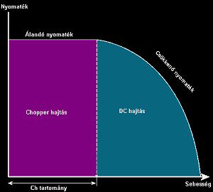
(turque-curve)
The stepping motors can also be used in the DC range, but their
torque will quickly fall if the speed is increased.
The Chopper range can be extended only by raising continually the power supply voltage switched onto the motor.
However the Controller must be able to control the current even with a motor coming to a halt
(when the speed is 0!), when the electric resistance is only the Ohmic resistance of the motor,
which is only a few Ohms.
How wide is the range that the Controller is able to control is very important and it is characterized by the so-called Tuning Factor. It shows how much fold of voltage the Controller is able
to control for a specific motor. If a voltage higher than this value is switched on to the motor
then the Controller will not be able to control it,
and the motor will be overheated. Profi2M Controller works with maximum 25-fold
of a Tuning Factor.
![]() Designing the power supply voltage of the
motor:
Designing the power supply voltage of the
motor:
Calculation of the voltage:
The Tuning factor is a multiplier depending on the inductivity of the motor.
The higher is the inductivity of the motor, the smnaller is its tuning factor.
The Controller switches on and off the coils of the motor at a high frequency, so that
the nominal current could be provided. These switching on and off generate very high
inductive voltages. The FETs of the power transmission bridge are protected by their built-in
supressor diodes (they led away these indictive voltages), this process produces
much heat. The higher is the inductivity of a motor, the more heat is produced (which causes a warming-up).
This warming-up heats the heat-sink of the Controller, therefore the smaller the inductivity of a motor is,
the higher voltage-ratio it can endure.
The Tuning Factor is the quotient of the motor power supply voltage and the base voltage of the motor
(T=Upow. supply / Umotor ).
The use of motors with small inductivities must be aimed, or if it is possible (e.g. in case of
8-wire motors), the inductivity can be reduced by paralell-connecting the coils.
As there is no data available on the motor inductivity in many cases, and it cannot be measured in a correct way, from the Ohmic resistance of the motor-coil conclusions on its internal indictivity must be drawn (it is not a perfect method, but it can be used). According to a rule of thumb, the higher of the Ohmic resistance of a motor-coil, the higher can be its inductivity (high Ohmic resistance = thin wire and many windings -> higher inductivity).
The following table gives practical information on the relationship between the base voltage of the motors and the maximum suggested value of motor power supply voltage:
| Base voltage of the motor: (voltage written on it) |
Recommended motor power supply voltage: (maximum tuning voltage) |
|---|---|
| 1V | 20V |
| 2V | 40V |
| 3V | 45V |
| 4V | 45V |
| 5V | 45V |
| 6V | 45V |
| 8V | 45V |
| 9V | 45V |
| 10V | 45V |
| 11V | 50V |
| 12V | 50V |
| etc. | ... |
![]() Attention!
A voltage of 50V cannot be exceeded! Take care of the possible overvoltage of the unloaded
power msupplies!
Attention!
A voltage of 50V cannot be exceeded! Take care of the possible overvoltage of the unloaded
power msupplies!
An example:

The base voltage of the motor is 4V and its nominal current is 5A.
The base voltage of the motor in the example is 4V. According to this the maximum applicable tuning voltage is ~45V. So a power supply with 45V would be the most suitable for this motor. By applying a transformer of 32V, the voltage would rise about up to 45V after rectification and thoroughful filtering (by a capacitor of min. 1000uF/A).
Of course the maximum applicable power supply voltage is 50V, this value must not be exceeded in any way.
The nominal current of the motor is 5A. In case of P2M this must be adjusted by the potentiometer trimmer (1.4×RMS=7A) of the card where the motor is connected (see description) (on the card marked by A, B, C or D).
Designing the current load:
When the current demand of the motor power supply is designed the nominal currents of the motors and the fact
that our system is a micro-stepping system must be taken into account.
The safest design would be if the double of the nominal current of each motor were taken
(because of the double-excitation system each stepping happens by the excitation
of 2 coils) and these values were summarised. This would come up to a very high value,
(e.g. in case of 3 motors with a nominal current of 2As the current demand would be 3×2×2=12A, say at 30V, it would result in
a transformer with a power of 360W). It is unnecessary.
In the practice perfect synchrone never occurs,
(or if it occurs it stays up for a very short time), as well as because of the PWM regulation
the duty cycle of the currents is continually changing (it is hardly ever 100%). Therefore it is safe to design
with the half of the above-mentioned current value (it is 6A in the example).
In the practice this value has the necessary reserve.
For the very short time for that the total synchrone would stay up, a capacitor with a higher value can provide the needed current without any problems (it must be at least 1000uF/A, but capacitors with higher value can also be used)!
Information on connection and adjustment of the motors can be found at in the description of the Controller.
![]() Micro-stepping:
Micro-stepping:
The micro-stepping technique gets through the excitation gently from one coil into the other (in sinusoid form), therefore most of motor resonances disappear. The stepping between two coils are performed by the DSP by exciting the coils with different excitation ratio. The ratios applied are from tables of trigonometrical functions, so their value is constant.
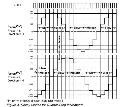
(excitations of 1/4 stepping in %s)
The excitation table is designed for an "ideal" stepping motor. In the practice the coils, poles, magnets of the motors are not perfectly identical, therefore they react not always according to previously expected way for the excitation. This may result in deviations (errors) between the angles theoretically intended and realised in the practice.
This means that not each of the motors can be used with the finest
micro-step. The motors with poorer quality will set in with bigger and bigger angle-errors.
This error will be 0 for a whole revolution, but the internal steps may not be uniform.
In the practice micro steps bigger than 1/4 may be substantially distorted, therefore
it is useful to test this problem previously in case of CNC machines with a small gear ratio (it is strongly motor-dependent).
The micro stepping system is a theoretical possibility, which can be used either with success or
only with bigger errors depending on the motor and on the power supply voltage.
The advantage its application is first of all the smoother (resonance-free) operation
and the more dynamic acceleration. It does not replaces the suitable gear ratio of CNC
machines.
![]() Software:
Software:
The use of Mach CNC operation softwares is strongly recommended. These programmes have the smoothest control at present, whose quality determines basically the speed values that can be achieved by our system.
In case of use of Mach2 and Mach3 softwares it is recommended to switch on the "Enhanced Pulsing" option.

(Switching on Enhanced Pulsing option in Mach3 softwares)
This option further improves the smoothness of the stepping pulses, but it needs at least a PC with 1Ghz CPU.
The Controller is not sensitive for the pulse timings of the Mach softwares.
(Pulse data of Mach3)
For the sake of safety it is recommended to adjust 2 for both pulse data!
Activation of Sherline mode is not necessary.
In case of very long (>5m) LPT cable it is not recommended to switch on the Sherline mode
(because of the possible signal dumping).
![]() Speed tuning of CNC
machines:
Speed tuning of CNC
machines:
In case of a new or rebuilt machine both the Controller (Profi2) and the CNC programme (Mach3) must be coordinated.
After allocation of the communication ports (bits) of Mach3 (see at
in the description of Profi2B)), the
measurement unit (mm) and the calculated resolutions must always be first adjusted (any adjustent of speed
cen should only be carried out only the knowlidge of these values). Do not forget to store these values
for all the three axes separately (see at
in the description of Mach3).
After that the maximum speed of each axis must be determined. The search for the maximum speed happens proceeding from the lower values towards the higher ones at relatively low accelerations. In the course of the tests the axes are driven manually (by the means of the keyboard) and their movement is observed. The speed is gradually increased and the speed value when the motor comes to a halt (it is screaming but does not rotate) is observed.
To be able to tune well the stepping motors and to understand the behavior of our system, it is necessary to know the (mechanical) moment curve of our system. It is not the numerical values, but their rerlationship what is interesting.

(moment curve of a complex system)
In the figure the moment curve of a unit consisting of a CNC axis and of a stepping motor and of Profi2M CNC Controller can be seen.
Caption to the figure:
- "Moment of the mechanical braking force" = brake reacting force of the axis as the function of the speed,
- "Actuation" = the minimum moment necessary to move the mechanical parts,
- "Torque of the stepping motor" = the resultant torque of the motor and the Controller,
- "Chopper range" = is the range that the motor and the Controller are able to hold at a constant torque,
- "DC range" = here the motor operates as a synchronous motor with a more and more decreasing torque,
- "Maximum speed" = the intersection of the loading and driving moment/torque, this is the highest machine speed available,
- "Kipping point" = its place is determined by the motor power supply voltage. It can be shifted (raised) proportional to the Tuning Factor along the axis of the speed,
- "Maximum starting speed" - without acceleration (in a pulse-like way) above thbis value the motor does not operate.
In the figure it can be seen that the use of acceleration is extremely important,
as the curve folds back and the motor can take up the revolution without acceleration immediately only in
a narrow ramge of speed.
By applying suitable acceleration the whole curve can be used.
Do not forget that the jerky operation (see at
KCam4) means sudden starts and stops,
i.e. starts without acceleration. Therefore stepping motors with KCam4 can only
be used at 0 maximum starting speed. The same is the situation if the acceleration
in Mach3 is adjusted to the maximum (Accel).
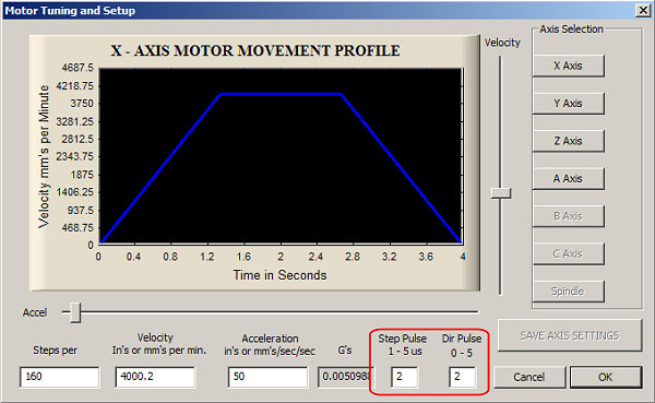
(Motor tuning screen of Mach3)
Recommended pulse data: Step Pulse=2, Dir Pulse=2.
Those who use the control for foam cutters can apply slow acceleration ( because of the technology), but even they also have to apply a minimum acceleration, if they want to use the motors in the whole range.
The exact timings of the Step pulses provided by the PC are responsible for the smooth operation of the motor. In case of Mach2 and Mach3 this is performed by the CPU with help of the mother board timers, which means, (unlike software timings such as e.g. KCam4) a high level of stability. As the Step signal is generated by the CPU, its load may influence the uniformity of the signal. If it is possible, do not run external programmes with high CPU load during CNC movements. However, the uniformity of the Step signal can be further increased by switching on the "Enhanced Pulsening, which means a little plus CPU load (it is worth doing so). To achieve suitable tuning the minimum CPU speed demanded by the manufacturer must be provided (as Mach3 itself means a high load for the CPU). Many other programmes are operated in the background by the Windows OS, therefore it is worth taking account this too, (ideas for optimalisation can be found at http://www.machsupport.com/artsoft/support/support.htm).
From the moment curve it can be read that normally the maximum available speed always falls into the DC range. Our motor is properly operated when its coming to a halt because of the loading moment is not long before the blocking of the motor operated without any load (if it is above 75%, then it is very good).
It is also important to know that (though the torque falls) there is no step-loss in the DC range. Should the stepping motor fall out of synchrone it would immediately block because its folding-back type moment curve. This phenomenon is spectacular and immediately can be observed. During tuning this point should be searched for (blocking). The the particular axis of the Mach3 must be adjusted slightly under this point (where the motor still rotates stably).
It is important to check the whole moving range at this speed after the adjustment
(for fear that the mechanics should sieze somewhere and should block there).
If each axis has been measured, adjusted and chacked, then all the axes must be checked again but
this time the movements should be performed at the same time on all axes.
This is necessary to get information on the voltage drop of the unstabilized motor power supply voltage
(in this condition the motors run at a little lower voltage because of the higher load)! If it is necessary,
reduce the speed values.
This adjusted maximum speed is the travelling speed of the particular axis,
it is not suitable for finishing (except for laser and plasma).
At that speed finishing is no longer performed (it is too fast), therefore it is excellent for fast moving
(positioning).
In case of Mach softwares the manual fast moving can be performed by SHIFT + arrow keys, or SHIFT + Page Up/Down keys.