(4D, kompact, bipolar, micro-step stepping motor controller)
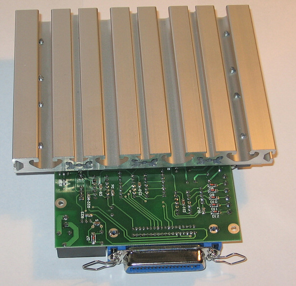
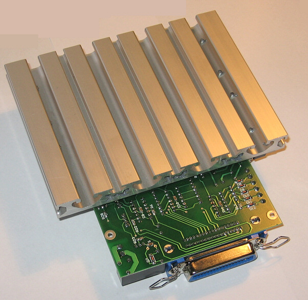
![]() H2 PCB CNC Controller
H2 PCB CNC Controller![]()
(4D, kompact, bipolar, micro-step stepping motor controller)
![]()
![]()
Modified: 2010. április 20. kedd
|
Content: |
|---|
| Introduction |
| General Description |
| Power Supply |
| Stepping motors that can be used |
| Connection of Motors |
| Adjustment of Motors |
| Inputs and outputs |
| Adjustments on the PC side |
| Ordering |
| Further information, add-ons: |
| H2 Motortuning (Hungarian language) |
| E1 expansion card (Hungarian language) |
| E2 expansion for JediCut, GMFC foam cutter (Hungarian language) |
H2 PCB Stepping Motor CNC Controller is the smallest member of a new generation controller family. Because of its compact build-up, it is the ideal solution to build hobby, or small CNC machines. In the course of its development the possibility of future extension and as well as the average demands based upon long time experiences have also been taken into account. H2 Controller is and integrated-build-up, all-in board CNC controller. It contains 4 micro-step stepping motor-driver, input and output interface, an expansion port, as well as a switching power supply. It is directly connected to the LPT (printer) port of the computer and it operates the CNC mechanics with the help of softwares (e.g. Mach3) running on the PC. It can be used to build milling machines, turning machines foam cutters and other CNC machines.
Main technical features (PCB V2.0):
- Step/Dir system, controlled through the LPT port, stepping motor controller,
- 4D (with 4 motors), compact build-up,
- 2-phase, bipolar, micro-step motor control,
- Micro-step values, selected by jumpers: 1; 1/2; 1/8; 1/16,
- Power-output with maximum 35V, 3.5A DC for each motor,
- Mixed mode current decay with PWM regulation,
- Silent holding path operating mode,
- Maximum 100kHz stepping frequency,
- Software controllable motor-rest,
- 4-range, jumperable, motor current regulation,
- 5 input ports (prepared to use end position and digitallable switches),
- 1 relay output (one-pole, maximum load 230V, 3A),
- 2-bit TTL expansion port,
- Build-up that needs only one power supply voltage (with integrated switching digital power supply),
- Protection against overheating,
- Installed cooling,
- Two-sided, partly SMD PCB
CNC control softwares that can be used:
- Mach3 CNC (Win2000, XP) [recommended],
- TurboCNC (DOS),
- WinPC-NC (XP),
- CNCGraf (DOS),
- JediCut,
- GMFC,
- CeNeCe,
- Stealth Plane Works: FoamCutter,
- etc.


(Picture Gallery. Click to zoom.)
Please see Compact style:
![]()
(H2 Compact CNC Controller)
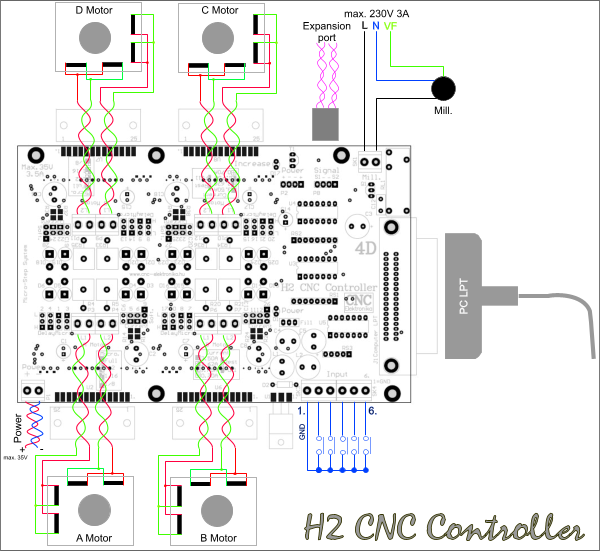
H2 CNC Controller can be used to control machines with 1, 2, 3 or 4 axes (it is not obligatory to use all the axes). In case of using Mach3 the logical assignation and synchronous operation of axes can be solved (e.g. for operation of 2D, 4-motor foam cutters, 2 motors can work at the same time).
(H2 system)
1 stepping motor can be connected to each motor-driving channel (A; B; C; D).
Within the motordriving channel, the serial or parallel connection of stepping motors is
not recommended.
Maximum 5 independent push-button, switch, endposition sensor can be connected to the
input port of the controller. The inputs are of Schmitt-trigger type, protected by diodes and
contain an internal pull-up resistor of 1 kOhm. Their state are inverted and fed to the PC through
the LPT port. Its function is entirely determined by the CNC software running on the PC.
A device (e.g. milling machine motor, cutting thread, etc.) can be directly driven (or can be switched) through the relay output.
The relay provides a one-pole separation (in case of applying a device, which needs 230 V,
a 2-pole auxiliary relay must be applied).
The Signal connector is a 2-bit, TTL type output expansion port. This is also of
Schmitt-trigger type and inverting looking the signal from the PC side. It can be used to control the fifth axis,
(as a Step/Dir output), for a Charge-Pump circuit, frequency changing revolution control (of PWM type),
or for a relay expansion output.
Its operation is entirely determined by the CNC controlling softwares.
A standard LPT cable (printeer cable) must be used between the PC and the Controller.
The use of a good-quality shielded cable (its maximum length is 3m) is recommended.
The controller needs only one power supply voltage, that of the power supply voltage of the motor. It generates
all the voltages that are needed for the electronics. This voltage does not need to be stabilised, only the rectification and
filtering is needed.
Further information about the design of the power supply can be found in the following.
The cooling of the controller must not be blocked, in case of placing the unit in a case, application of a fan
may be necessary. It is recommended to apply a fan running at 24 V, and it can be operated from the
24 V AC coil of the transformer.
(Mechanical fixation using screws of M8 and M5)
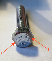
(In case of edge-fixation the screw of M5 must be filed a bit at an angle of 45°,
on the side)
A The controller needs only one power supply voltage. It does not need to be stabilised, only rectification and filtering is necessary. The allowed voltage range is 12-35V DC. Exceeding 35V may lead to damaging of the controller. It is recommended to use an insulating safety transformer of 230/24V AC voltage, with a rectifying bridge of minimum 20A and with a capacitor of minimum 10 000 uF. It is also recommended to apply a delayed action fuse of 10A between the power supply and the controller.
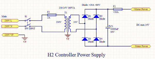
(the schenmatics of the power supply)
A power supply with a 160VA, 230/24V transformer is able to feed all the 4 motors at the maximum load of 3.5A (because of the PWM control). It is extremely important that the power supply unit must not exceed the 35V DC motor power supply limit (even in unloaded state).
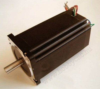
(stepping motors)
The controller has a 2-phase bipolar motor power output, therefore all types of 2-phase motors can be used. So that the highest possible revolution number could be achieved and because of the micro-step stepping, it is recommended to use bipolar motors with the possible lowest base-voltage. The base-voltage of the motor is the voltage, which is indicated on the data-sheet as the voltage of the coil. The most optimal drive can be achieved if the power supply voltage of the controller is held at 30-35V and the base-voltage of the bipolar motor applied is under 3V. If the motor is a 8-wire type (universal), then parallel connection of the coils is recommended.
Recommended types of stepping motors:
| Type of the motor | Its holding path torque [Nm] |
|
23LC041-025-8W-xx-0.5 |
0.5 |
|
23LC051-025-8W-xx-1.0 |
1.0 |
|
23SM056-028-8W-xx-1.3 |
1.3 |
|
23LC064-025-8W-xx-1.5 |
1.5 |
|
23SM080-028-8W-xx-1.7 |
1.7 |
|
23SM100-030-8W-xx-2.0 |
2.0 |
|
23SM112-030-8W-xx-2.5 |
2.5 |
Further information on the motors can be found here.

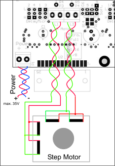
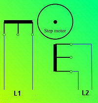
(motor phases and motor power supply voltage connections)
- The controller has been designed to apply 2-phase, bipolar (4-wire) motors.
In case of bipolar motors the matching phase-ends must be connected to the L1 and L2
terminals. The phase order does not count, as the rotation direction can be changed within the CNC sofwares.
The EMI noise produced by the motors can be substantially reduced by pairing the matching motor-coil ends,
therefore their pairing is strongly recommended.
Take care of the short circuit-free connection of the wires.
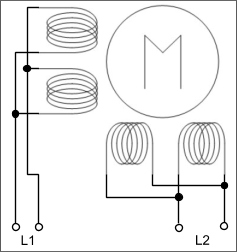
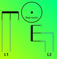
(connection of bipolar motors)
Possibly the modern, low-voltage and inductivity 8-wire (universal) motors should be preferred. The choice of the recommended motors can be found here. It is important that in case of 8-wire motors the coils belonging to the same side must be parallel connected. The coil-begin must be connected to coil-begin and coil-end must be connected to coil-end. The color identification of the wire ends can be found on the data-sheet of the motor. The current to be adjusted is about 1.5-fold of the coil current.
(Connection of 8-wire, universal motors)
The performance of older, used (might be universal type) motors with high base-voltage and inductivity is substantially smaller. In case someone insists on their use, then there are 2 possibilities for their connection.
- It is also possible to connect unipolar (5-, 6-wire) motors. In this case there are 2 possibilities:
 |
 |
| A | B |
|
(Possibilities of the connection of unipolar motors) |
|
There are substantial differences between the 2 modes of connection.
Mode A : at lower speed values a torque of about 20% higher than that of normal can be achieved (twice as much windings are excited), but the available maximum speed value is substantially smaller (because of the twice as much inductivity value and that of the base volatge). The inductivity and base voltage of the motor is twice as much as that of the specification. The current to be adjusted is the nominal current of the coil.
Mode B : all specifications are the same as those of the oroginal ones (higher speed values, nominal torque values). The current to be adjusted equals with the value indicated on the data-sheet. It does not count which coil-end is connected to the middle end to the controller, (it influences only the rotation direction). This is the preferred mode of connection.
Adjustment of the motor current:
The motor current values for each axis can be adjusted by setting 2 jumpers to one of 4 positions. The jumpers for each axis can be found in the Current field (2 pieces of double jumpers).
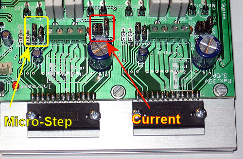
(Current
jumper field)
|
Jumper identifications: |
||
| 1 |
position 1-2 |
|
| 2 | ||
| 3 | ||
| 1 |
position 2-3 |
|
| 2 | ||
| 3 | ||
| 3.50A | ||
| 2.62A | ||
| 1.75A | ||
| 0.70A | ||
(adjujstment of the motor current by the Current jumpers)
The current-rest of a given axis can be determined by the No 3 terminal jumper with the notice "Soft." . In "Rest" position the motors will be down-regulated in standing position (down to 0.7A), supporting by that the better cooling of the motors and that of the controller. This down regulation is emitted when the lowest current value (0.7A) is adjusted. The down-regulation is performed by the CNC software, therefore the correct set-up in the software is also necessary.
In "Full" position of the jumper the motor excitation determined by the Current jumpers is continually realized (there is no rest). The use of this mode is suggested if the CNC control software is not able to control the motor rest.
|
Rest |
|
|
Full (continual excitation) |
|
(the jumper of the motor rest (Soft. field))
The state of the motor excitation is indicated by a LED with the notice "Increase" ,which can be found on the controller. Its continual lighting means that the motors are running with full excitation. The correct function of the CNC software can be checked by that (during stepping it must always light if the rest function is set by the jumpers [Rest]).
In the course of determination of the motor current to be adjusted, the data-sheet of the motor must always be taken into account. In case of 8-wire (universal) motors 1.5-fold of the nominal coil current must be choosen if the coils are parallel connected (which is recommended). The excitation current must be jumpered by approaching from the higher values. E.g. : if the motor current to be adjusted is 3A, then the Current jumpers must be set to the position of 3.5A. If the current to be adjusted is 2.5A, then the position of 2.62A must be choosen.
Recommended adjustments of the motor current:
| Type of the motor | Holding path torque [Nm] |
Setting value of the Current Jumper [A] |
|
23LC041-025-8W-xx-0.5 |
0.5 | 2.62 |
|
23LC051-025-8W-xx-1.0 |
1.0 | 2.62 |
|
23SM056-028-8W-xx-1.3 |
1.3 | 3.50 |
|
23LC064-025-8W-xx-1.5 |
1.5 | 2.62 |
|
23SM080-028-8W-xx-1.7 |
1.7 | 3.50 |
|
23SM100-030-8W-xx-2.0 |
2.0 | 3.50 |
|
23SM112-030-8W-xx-2.5 |
2.5 | 3.50 |
More detailed information on the motors can be found here.
Adjustment of Resolution (micro-step):
The extent of stepping of motors (micro-step) can be adjusted by two 3-level jumpers in the "Micro" jumper field (that can be done for each axis).
(Micro-Step jumper field)
|
Full |
||
|
1/2 |
||
|
1/16 |
||
|
1/8 |
||
(positions of micro-step jumpers)
It is preferred to use of 1/16, or perhaps 1/8 step so that the resonance-free operation could be achieved. If the CNC control software cannot handle the stepping frequency, then it is suggested reducing the value of micro-stepping.
| Micro-step value |
Resolution of the motor [in case of a motor with 1.8°] |
| Full | 200 |
| 1/2 | 400 |
| 1/16 | 3200 |
| 1/8 | 1600 |
(Number of steps for a full rotation)
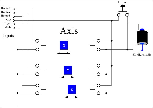
H2 Controller has several inputs and outputs, all of them are monitored and used for different purposes by the applied CNC Control programme. Therefore their task depend how they are set within the programme. Each of the control programmes identifies the inputs and outputs (ports) based upon the pin number of the LPT port belongs to the port. Towards the end of the description there will be a summerising table, which shows the LPT pin-number allocation of the given ports and motors.
Inputs:
H2 CNC Controller contains 5 inputs. The inputs are available on the Input terminal. Pin 1 of the terminal is GND, the input ports marked 2 - 6 can be operated by switching them to that (No 1) pin.
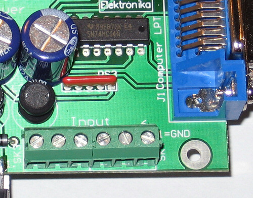
(Input terminal)
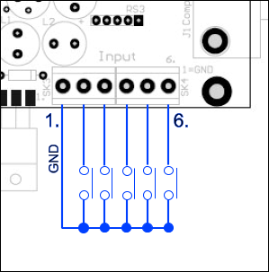
(connection of the inputs)
(sample circuit to demostrate the use of inputs)
The sample circuit presented above supposes the use of Mach3 CNC controlo software, using this software these functions are also available. Further information can be found in the description of the control softwares.
Outputs:
The Controller has two types of outputs:
- Relay output,
- Signal port (2-bit, TTL-type output).
Relay output:
The relay output is potential independent, can be loadad with 3A at maximum 230V. The relay provides one-pole separation. Its pins are available on the Mill. terminal.
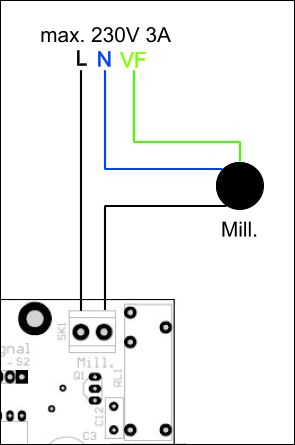
(relay output)
It can be used to control a milling machine motor, or switching any other device through the CNC software. In case of switching higher voltage than 50V, the safety separating instructions prescribed in the referred standard must be taken into account (applying a 2-pole-separating auxiliary relay)!
Tipps for assembling the circuit:
A 40 mm long peg, bent at 90° can be used to lift the plate of the terminal:

(device to "dilate the terminal")
Signal and Power connections (Expansion port):

(Expansion port)
The Signal connector and the Power connector next to that are the Exapnsion port of the Controller. The Power connector is to provide the power supply voltage for the expansion circuit (+5V), with a current load of maximum 200mA.
| Vcc | GND | GND | Vcc |
(Pin allocation of the Power connector)
A GND=0V, Vcc=+5V.
On the Signal connector 2 TTL-type outputs can be found. The outputs are inverting from the side of PC. Their fan-out is 10 LS TTL inputs.
| S1. | GND | GND | S2. |
(Allocation of the Signal connector)
The 2 bits can be used for external controlling purposes (PWM, relays, fifth axis, etc.). Its bit allocation can be found in the summarising table. The connectors are marked on the PCB with notices referring to their function.
Here is an add-on card to control Charge Pump PWM-type frequency changers:
E1 expansion card:

(Charge Pump and PWM-type frequency changer
E1 card)
E2 expansion card:
(JediCut and GMFC compatibility)
Their setting-up on the PC side (software):
![]()
All CNC Control software indentifies the given ports, motors, and functions based upon the LPT pin-number. these must be set-up within the softwares.
| I/O function: | Function/connector: | LPT pin number: |
| Output of motor A | Step | 3* |
| Dir | 2 | |
| Output of motor B | Step | 5* |
| Dir | 4 | |
| Output of motor C | Step | 7* |
| Dir | 6 | |
| Output of motor D | Step | 9* |
| Dir | 8 | |
|
Inputs |
GND/1. | - |
| 2. | 10 | |
| 3. | 11 | |
| 4. | 12 | |
| 5. | 13 | |
| 6. | 15 | |
| Outputs | Relay (Mill.) | 14 |
| S1 (Signal) | 1* | |
| S2 (Signal) | 17* | |
|
Rest (Current Hi/Lo) |
16* | |
| The pins marked with * are of inverting type. | ||
(summarising bit-allocation table)
Detailed Mach3 set-up:
VIDEO:

(Set-up of Mach3 for H2 CNC
Controller video (wmv, 19MB))

(Mach3 CNC control software)
The set-up screens can be reached from the Configuration menu of Mach3 (proceeding from the top to the buttom).

(converting measurement units to mm)
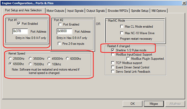
(Port, speed and Sherline 1/2 Pulse mode)
Attention! If the PC isn't fast enough, then the motor will begin to jerk at the speed that the frequency of 65kHz belongs to (the speed is too high for the system). In this case the speed must be reduced and maybe that smaller value of micro-step should also be choosen. The set-up of Sherline 1/2 Pulse mode is very important. Whithout this setup the operation of the controller may be uncertain. In case of note-books the value of the Port Address may differ from the base setup. Further information can be found at using the second LPT port! In case of built-in LPT port the base setup can be used.

(Step/Dir bit allocation of motors)
Attention! Everything must be filled in in this way. If Step Low Active is not set,(this inverts the Step signal), then the operation of the controller will be uncertain.

(handling of the inputs)
Estop is fixed, but the others can be flexibly handled. The function depends on the configuration
(this is just an example among the many possible configurations).
The above described adjustment supposes the pins from number 2 to number 6 on the input ports
to be end-positions. According to the adjustments:
pin No 2 on the terminal (pin No 10 on LPT) = the parallel connected maximum endpositions of the 4 axes,
pin No 3 on the terminal (pin No 11 on LPT) = the minimum end position of axis X (and that of X Home at the same time),
pin No 4 on the terminal (pin No 12 on LPT) = the minimum end position of axis Y (and that of Y Home at the same time),
pin No 5 on the terminal (pin No 13 on LPT) = the minimum end position of axis Z (and that of Z Home at the same time),
pin No 6 on the terminal (pin No 15 on LPT) = the minimum end position of axis A (and that of A Home at the same time).
Using the above-written adjustment the system is also able to record and search for the automatic 0 point (Home) (even with the co-existance of other adjustments).

(outputs)
The Current Hi/Low is responsible for resting the motors, so its set-up is compulsory. The output No 1 pin controls the relay, its setup is OK. The output No 2 pin and No 3 pin are the bits of the expansion port of S1 and S2, its setup can be handled flexible and there are many possible variations of its setup (PWM, relays, fifth axis, etc.). The knowlidge of the possibilities offered by the software is necessary for their aplication.
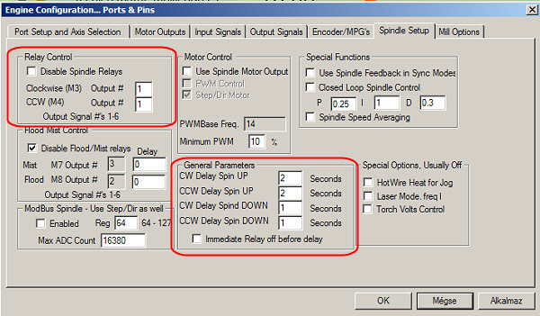
(Usage of Mill. relay)
The data necessary for the usage of the relay. The rev-up- and rev-down time of of milling machine motor can be geiven too. The rest of the fields can also be flexible handled (depending of the setup of the output it may also be necessary to handle them too).
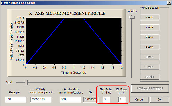
(pulse width)
It is also "compulsory" to adjust them. They are needed for the correct operation of the controller. The other fields depend on the specifications of the CNC machine. The step number necessary for 1mm length of movement of the machine (which depens of the gear and that of the micro-step adjustment) as well as the the maximum speed of the machine and the acceleration of the machine must also be given here. More detailed description can be found on in the user manual of Mach3 .
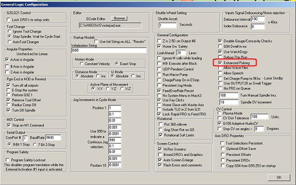
(adjustment of improved quality of motor operation)
By switching on the Enchanced Pulsing the quality of the operation of the a motors can be further improved (demanding some more CPU load). If the machine has enough CPU power, it is worth using this option.
![]()
H2_Setup.zip
(Mach3 setup, it can be downloaded in one file)
This file must be unpacked into the directory of installed Mach3 and Mach3 must be started and the H2 Controller Session Profile must be selected (with the Mach3 Loader).
![]() Further
information on the adjustment and usage of motors can be found
in the description of H2 Motor tuning.
Further
information on the adjustment and usage of motors can be found
in the description of H2 Motor tuning.
![]() The description of softwares
and information in Hungarian can be found on in the Info
base!
The description of softwares
and information in Hungarian can be found on in the Info
base!
![]()