(Technical description of P2C CNC Base Card)
![]() Profi2C I/O Card
Profi2C I/O Card![]()
(Technical description of P2C CNC Base Card)
![]()
Modified: 2010. január 25. hétfő
Profi2C is a developed version of P2B I/O card. It is a base card, which makes connection between the PC and the given axis-controllers and other peripherials. Its task is to provide a complete two-way galvanic separation, signal amplification, signal division and handling the plenty of I/O functions. It has been developed first of all to help Profi2 Quantum Servo controllers, but it can be used with other stepping-motor axis controllers too (e.g. MSD-XX-XX family).
P2C Card provides a real two-way and complete opto-coupled separation (with a double power supply). It is especially recommended for building plasma-cutters and other machines producing high EMI noise.
Main technical specifications:
- 4-axis, Step/Dir outputs (max. 4D),
- Two-way, complete galvanic I/O separation,
- High speed (1 MHz) digital optocouplers,
- Relieved and strehgthened LPT port handling,
- Independent double I/O power supply,
- Handling of 5 inputs (direct handling of switches, push-buttons),
- 4 relay outputs (max. 230V, 3A),
- 0 - 10V PWM, optocoupled convertertransformerátalakító (for frequency changers),
- Charge Pump security circuit,
- 4d 12V (max. 1000 mA) power supply for CNC logic circuits, axis controllers (for P2Q),
- Direct connection at the LPT port (Centronics),
- Full LED I/O feed-back signals,
- Jumperable functions,
- 230V built-in interference filter,
- Partly SMD-mounted PCB.
Picture gallery:
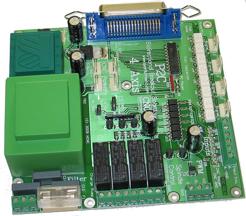
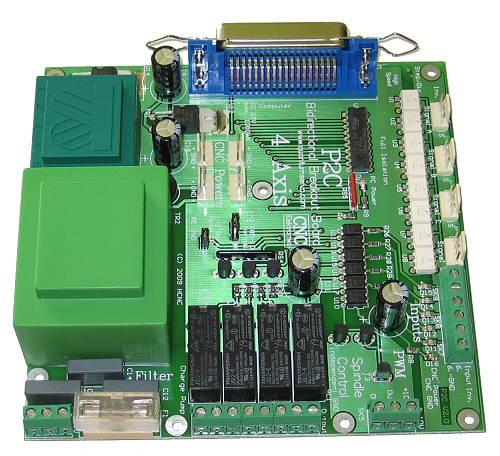
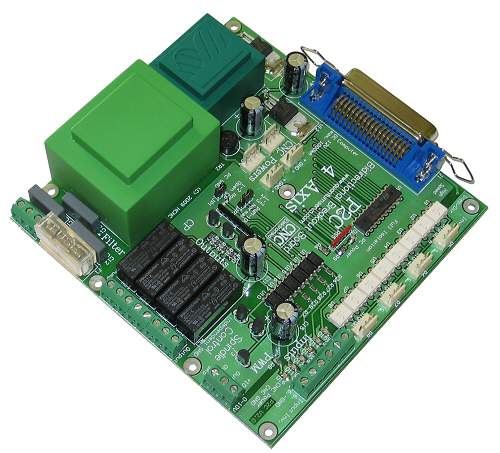
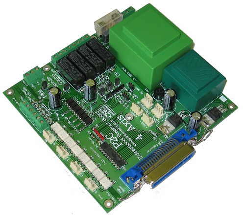
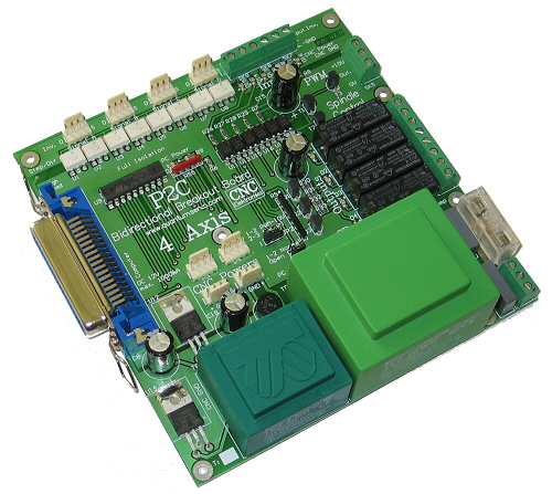
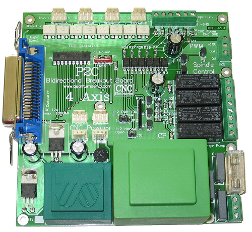
(click to zoom)
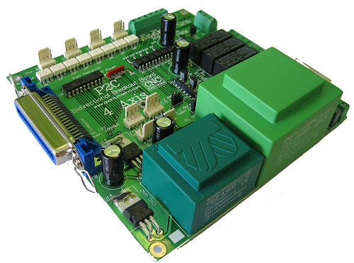
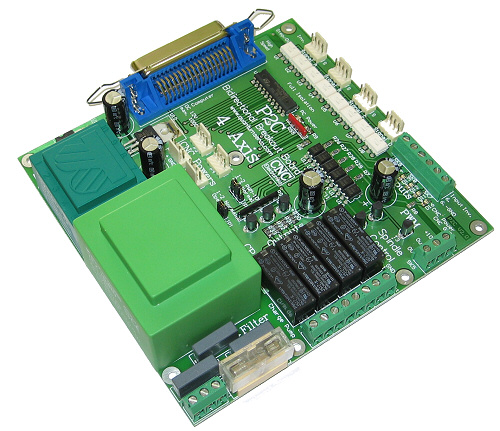
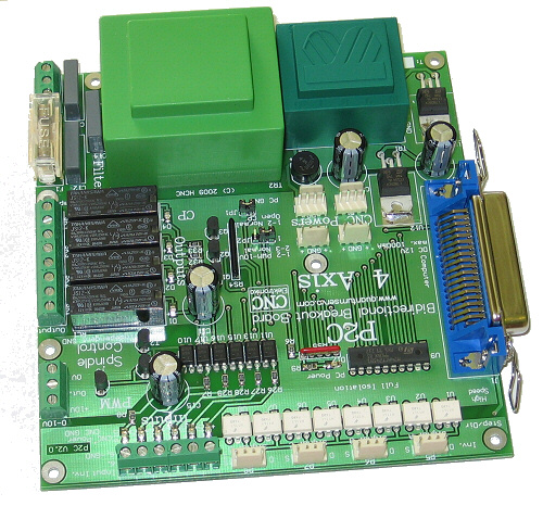
Its build-up:
The I/O card is built-up on a PCB of 143×147 mm. The number of the fixing srews is 7 (with 3.5 mm diameter boreholes).
All the input and output ports of P2C base card are galvanically separated from PC.
It provides Step/Dir signals necessary to run maximum 4 axis controllers.
Step carries the stepping data, Dir carries the data of directrion. Stepping-motor controllers and
servo controllers can also be connected. The outputs have TTL levels, so for ports that are not in use by the axes at present,
other type of control can be built-up.
Any kind of make contact can be connected to the 5 (TTL) input ports directly (e.g. end-position switches,
push-buttons, etc.). Its functions are decided by setup of the software controlling it.
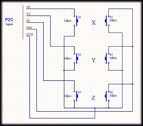
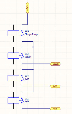
(Example: Connections of the end-position switches of a 3-axis CNC)
4 relay outputs can be used to control the motor of a milling machine, cooling, charging apparatus,
etc., while 2 relays can be selected to be used for normal relay functions, Charge
Pump and PWM. The selection can be adjusted by jumpers. The softwares must be setup according to the
position of the jumper (adjusting only the jumpers is not sufficient).
The Charge Pump funtcion makes possible to built in a security-interlock condition.
In this mode one of relays will operate only if Mach3 is running and it surveys the CNC control.
It is necessary because if Mach 3 is not running (or it is not running yet, e.g. when Windows is booting)
then the CNC machine being on can start without any control, which may lead to accidents as well.
The interlock can be realized by leading all the other functions through the
Charge Pump relay too, (this relay must be the first interlock), and the voltage can go to the other relays only after this relay.
If this relay is not operating, nothing can start.
(Realizing CP ínterlock)
The Charge Pump (CP) relay can only operate if Mach3 gives out the necessary signal (5 kHz square-wave signal). Both the jumper must be adjusted and the programme must be setup properly for this interlock.
PWM mode is a digital/analogue converter, which has been developed first of all to control the revolution number by frequency changing.
The software revolution control of the spindle (and any kind of such controls) can be realized by its application (either through the screen,
or by commands embedded into G-code). One can choose from the 2 modes (PWM mode and a normal relay mode) also by jumper.
The software also has to be setup properly. In normal mode it is a simple controllable relay, in PWM mode it is a 0-10V
converter (it takes the power supply from the device it is going to control).
The PWM connecting plug must be connected to the place of the potentiometer of the frequency-changing revolution controller,
It is galvanically separated from everything completely.

(Exapmle: Controlling frequency changers with the help of PWM)
P2C contains 4 unstabilized 12 V DC connectors too, which provides the power supply for
the axis controllersk (e.g. Profi2 Quantum
Servo Controller).
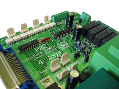
All the outputs and inputs have LED signals.
(LED signals, PWM converter and Charge Pump)
A simple (two-way) LPT printer cable connector can be connected to its standard Centronics socket. Because of the signal amplification it can be used up to a maximum distance of 5m.
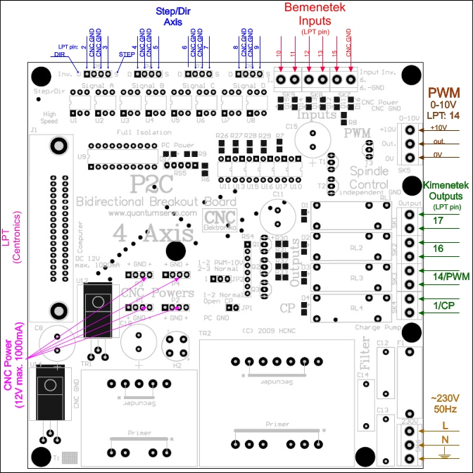
(I/O connections of P2C I/O Card)
The numbers indicated in the figure are LPT pin numbers to be given during the setup of Mach3 (and of other programmes).
(Connections, terminals)
Power supply:
The card gets the electricity from the electric network of 230V AC, 50Hz.
It is important to connect the protective grounding too, because the 230V filtering
can efficiently operate only if it is connected.
The power supply is protected by the fuse of 1A.
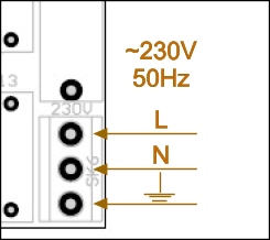
(mains connection)
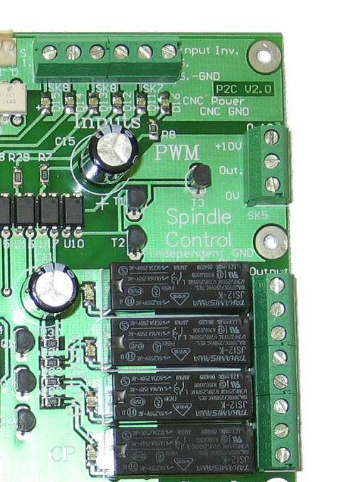
Relay outputs:
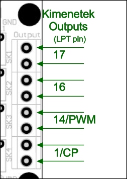
(relay make contacts)
The potential-independent make contacts of the 4 relays can be found on SK1 - SK4. They can be loaded with max. ~230V, 3A. The numbers presented in the figure are the pin numbers of the LPT port (They have to be inputted during setup). The relays are logically inverted.
PWM output (0 - 10V, for frequency changers):
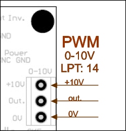
(potential-independent PWM-type converter for frequency changers)
It can be used for the revolution-number control of frequency changers. It coverts the PWM square-wave signal appearing on pin 14 of the LPT port to a voltage ranging from 0 to 10 V. To lead it onto the suitable input of the frequency changer, its revolution number can be controlled by a programme. Of course it can be used for other type of control too. Potential-independent outputs. +10V is the controlling voltage coming from the frequency changer, 0V is also the 0 V of the frequency changer (GND of the frequency changer), out is the voltage going to the frequency changer (0-10V, PWM-controlled). The output can be loaded with maximum 100 mA. The cable connected to here must be a shielded cable.
(The 0 - 10 V outputs of the PWM converter must be connected to the place of the speed potentiometer of the frequency changer)
Inputs:
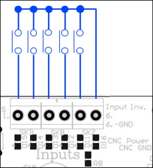
(input connections)
They can be used to control end-position switches, Home switches and other make contacts. They are TTL inputs with internal pull-up resistors. The contacts (end-position switches, push-buttons, antennas) can be directly connected to them. Their common pin is pin No. 6 CNC GND.
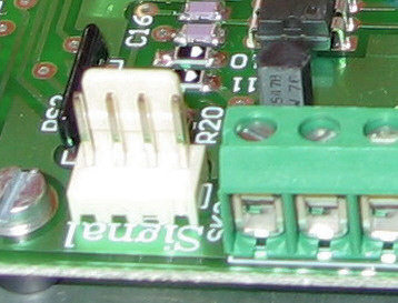
Step/Dir axis-controller outputs:
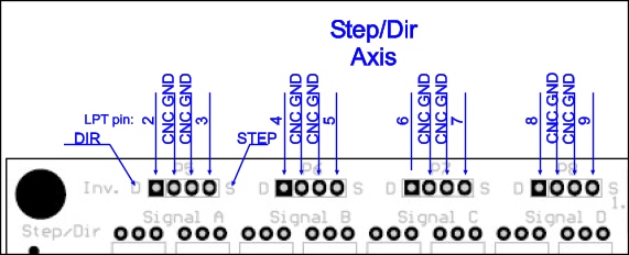
(4D axis-controlling outputs)
High-speed Step and Dir TTL outputs. They are able to drive maximum 4 axis controllers (their marking: Signal A, Signal B, etc.). The Step/Dir inputs of the individual axis controllers must be connected to them. They can be loaded with 50 mA at low level and with 2 mA at high level. The value of recommended pull-up resistor on the receiving side: 470 - 1k. They also can drive a second optocoupler too. (When MSD controllers are applied, the voltage must be reduced to 5V with the help of a small auxiliary circuit.). The Step/Dir inputs of Profi2 Quantum (Servo) can be connected directly to them. The side D of the connector contains the Dir signals, while the side S contains the Step signals (the two middle pins are connected to the GND of the CNC). The signals are inverted from the PC side.
(Signal input of Profi2Q)
The recommended cables for the connection are the cables used to connect a CD-rom to the audio system of the PC (they are shielded):
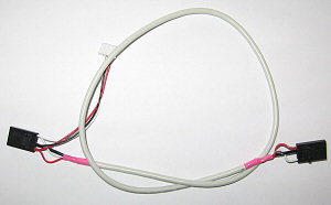
(shielded Step/Dir cables)
Connection of MSD-XX-X.X (made in China) stepping-motor controllers:
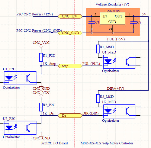
(Connecting-up the MSD-XX-X.X stepping-motor controllers using 78L05)
Or
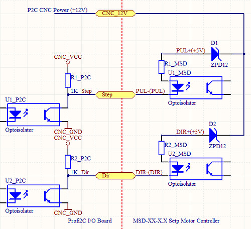
(Connecting-up MSD-XX-X.X stepping-motor controllers using Zener diodes)
To drive the double opto-separation it is necessary to produce 5V voltage (it can be realized either with a 7805 on a small PCB with some filtering, or with zener diodes of 12V must be placed before each input).
CNC Power supply connections:
On the card 4 CNC Power connections can be found (they can be connected using shielded cable), which produc voltages for the axis controllers (e.g. Profi2 Quantum), (in case of MSD it does not have to be connected). On the first and the last pin of the connector unstabilized but filtered +12V DC voltage is available, with 2 GND pins in the middle of the connector. It can be loaded (the 4 alltogether) with not more than 1000 mA.
(Signal, Power connections and jumpers)
Some of the functions are shared. To select them the 2 jumpers, which can be found on the card, must be used. The control software (e.g. Mach3) always must be setup according to the position of the jumpers.
| Jumper: | Position: | Function: |
| JP1 | 1-2 | normal relay (SK4) |
| open | Charge Pump (SK4) | |
| JP2 | 1-2 | PWM-10V (SK5) |
| 2-3 | normal relay (SK3) |
(Jumper settings)
Wrong Jumper - Mach3 Setup setting causes neither in P2C, nor in the PC any damage, (it causes only faulty operation).
(a 90° 40-mm nail as a tool for expanding terminals)
The shives of the terminal can be lifted by that again (if necessary).
The wires that connect the PWM 0-10V converter should be shielded. The shield must be connected
to the 0V pin of the frequency changer.
The input wires should be shielded too. The shield must be connected to the GND of the CNC.
It is forbidden to connect the GND of the PC to the GND of the frequency changer and to the GND of the CNC! The metal frame of the CNC machine and that of the frequency changer must be connected to the protective ground of the electric network!
The length of the LPT cable can be maximum 5 meters and it must be placed as fas as possible from the high-current wires.
| I/O function: | Terminal/connector: | Pin number of the LPT: | Type of the Logic: |
| Controlling output A | Signal A/Step | 3 | inverting |
| Signal A/Dir | 2 | X | |
| Controlling output B | Signal B/Step | 5 | inverting |
| Signal B/Dir | 4 | X | |
| Controlling output C | Signal C/Step | 7 | inverting |
| Signal C/Dir | 6 | X | |
| Controlling output D | Signal D/Step | 9 | inverting |
| Signal D/Dir | 8 | X | |
|
Inputs (with internal pull-up resistors) |
1 | 10 | inverting |
| 2 | 11 | inverting | |
| 3 | 12 | inverting | |
| 4 | 13 | inverting | |
| 5 | 15 | inverting | |
| 6 | GND | - | |
|
Outputs (relays, PWM) |
SK1 | 17 | - |
| SK2 | 16 | - | |
| *SK3 | 14 | - | |
| *SK4 | 1 | - | |
| *Charge Pump | 1 | - | |
| *PWM | 14 | - |
(bit-allocation table)
X - The user decides (direction changes).
* - Shared functions, they can be selected by jumpers.
Recommended minimum DIR tracing and Step pulse-width: 2 µS!
Mach3 setup:
The following description discusses the configuration of P2C - 4×P2Q. In case of other axis controllers the level of the Step logic and the pulse-length may be different.
![]()
P2C_Setup.exe
(Mach3 fast setup)
Installation: The file must be copied into the folder of the installed Mach3 (next to the exe file) and must be started. Overwriting must be permitted. Then, launching the loader of Mach3 a new profile appears: P2C. This must be selected.
Attention! In the course of the development of Mach3, after some time it may happen that the above-written fast setup will not be fully compatible with the new version of Mach3. This may lead to problems during operation. This version was developed to R3.043.000 of Mach3. It is recommended to check manually the settings after its installation.
Manual Setup:
Motor outputs:
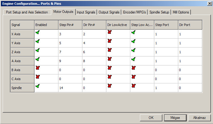
(Bit-allocation of the Motor and PWM Spindle)
The correct adjustment of the Low Active signal of Step is important. for the (P2Q). Everything must be filled in and ticked off according to the screen.
Inputs:
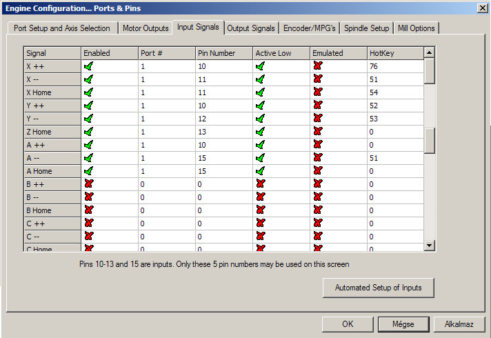
(handling of the switches, input)
If other functions are to be realized or the connection of the switches is different, then it must be rearranged according to the actual positions.
Outputs:
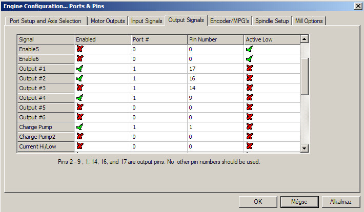
(output bits and Charge Pump)
If someone does not want to use the Charge Pump, then Output #3 can also be activated (one more relay will be available). Both of them cannot be used at the same time and the relating jumper on the card must also be adjusted.
(Jumpers)
Spindle Setup:
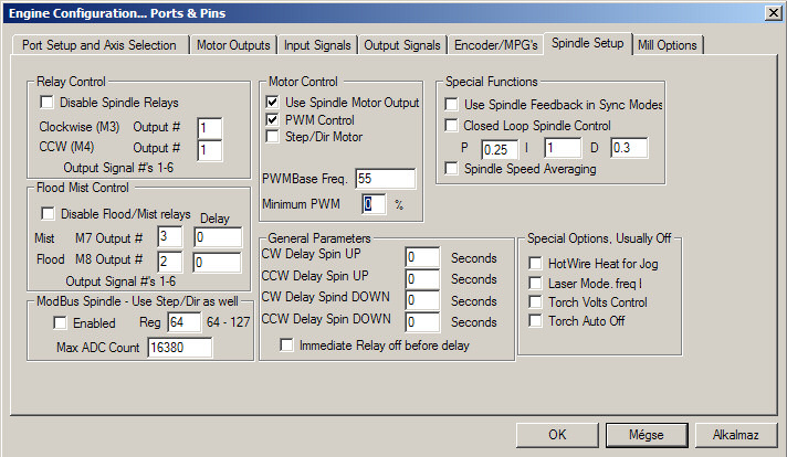
(handling of relays and PWM data)
Everything must be filled in according to the figure.
Motortuning:
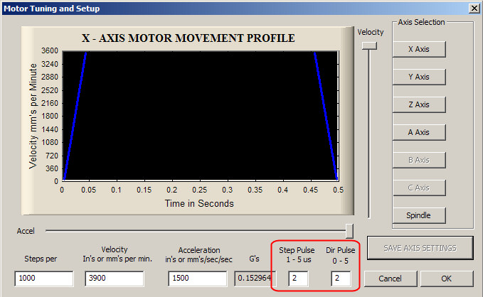
(pulse data)
If not a P2Q axis controller is applied, then it might be that it is necessary to increase the number 2.
Charge Pump:

(recommended adjustments)
The Charge Pump releases in case of activating E-Stop (recommended). Switching on Enhanced Pulsing (suggested) smoothes further running of the motors and it means a bit higherCPU load in return.
PWM:
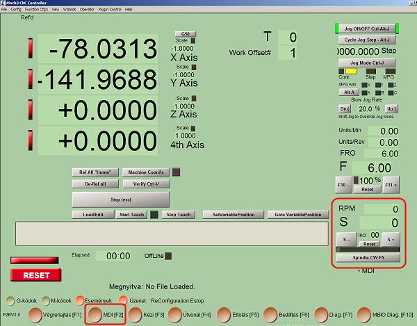
(Handling of PWM (MDI screen panel))
The revolution number of the frequency changer can be inputted in the field S (or by the command F in G code) after switching on the Spindle button
(it will emit the PWM signal based upon the ratio of the Puley adjustment).
An example: If puley stands at 8000 and 4000 is written to the filed S, then the duty cycle of the PWM
will be 50%, which results in 5V on the output (the frequency changer will run at the half value of the preprogrammed speed).
![]()