(Digital servo controller for DC motors with carbon brushes)
![]() Profi2
Quantum DC Servo Controller
Profi2
Quantum DC Servo Controller![]()
(Digital servo controller for DC motors with
carbon brushes)
Modified: 2010. április 25. vasárnap
![]() Profi2Q
& QDSP Description (pdf)
Profi2Q
& QDSP Description (pdf)
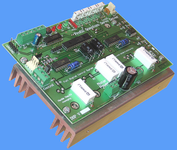
Profi2Q CNC Digital Servo Controller is capable to control DC servo motors with carbon brushes. It is suitable for both hobby-type and half-professional CNC applications. P2Q use QDSP IC, is a circuit, which is a high-speed, flexible, easy to use device, based upon dsPIC30F4012 microcontroller, for building servo controllers. The field of its application is first of all moving controllers of CNC-s, or performing any kind of regulation task demanding high precision and speed. During its the most optimal fit to the popular Mach CNC control programmes was a key issue.
Main features (V1.6.0):
- Step/Dir-system motor stepping inputs,
- Motor peak current limit 0.1- 26A,
- Continuous Power: 400W, max. 90V DC,
- Two-channel, symetric and assymetric incremental encoder inputs,
- Encoder processing: 2×, 4× modes,
- Programmable Encoder Digital Interference Filter (EDIF),
- Step signal multiplicator: 1× - 10× (step-multiplicator),
- Protection against motor overload: 1s - 7s (in a programmable way),
- Protection against overload of the controller (with readable temperature),
- Programmable integration time (95uS - 475 uS),
- Serial fine tuning (handling of the internal registers),
- Online error-level monitor (with ASCII or binary communication),
- Online PWM limit monitor in ASCII form,
- Error-level peakindicator (with ASCII 3s datalogger),
- Full PID motorcontroller algorhytm,
- Analogue P, I, D parameter-adjustment by potentiometer trimmers,
- Reduction of motor vibration,
- DSP performance: 120MHz, 30 MIPS, 16bit CPU, 40bit ALU,
- Full H-bridge control (with PWM and motor-brake modes),
- 16 bit PWM,
- Current limiting input,
- Adjustable Soft Error Limit buffer (1 - 200 Steps),
- Adjustable Hard Error Limit buffer (1 - 30000 Steps),
- Bandwith values:
Encoder signal frequency: max. 6MHz,
Step signal frequency: max. 1 MHz,
- Double Status signals by LEDs,
- Thermometer sensore,
- Error indication output (Fault),
- Emergency stop input (Stop),
- Numerous writeable and readable configuration registers,
- Firmware upgrade possiblity through ICSP,
- installed cooling,
- 2-sided, partly SMD mounted PCB.

Profi2Q CNC Servo Controller performs the servo control of DC
motors with carbon brushes by the means of a 2-channel incremental encoder
(symmetric or assymetric type). Because of the encoder-feedback a closed-loop
position regulation is realised.
Unlike stepping motor controls, here a regulation takes place, - therefore in
case of correct asdjustments - no steploss may occure. The control electronics
uses a lot more information, therefore a more intelligent drive-method can be
realized. The control (PID) forces the motor into the intended position (because
of the encoder the control always has exact information), and if it is not
possible (e.g. because of getting stuck), then this can be signalled to the PC,
so the user can be notified about the error, and he can prevent the error even
during work.
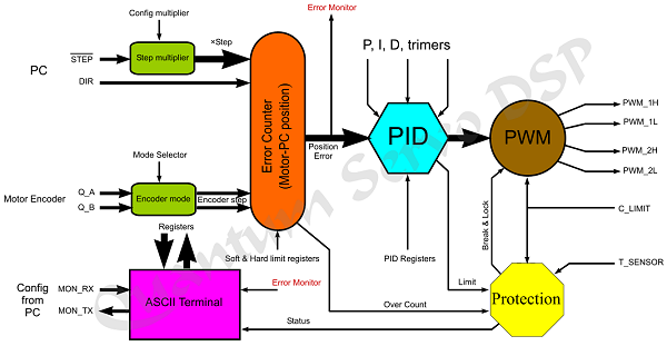
The computer makes the motor step through the Step/Dir inputs of P2Q. The Step signal is featured with negative logic (makes the motor step at falling edge). At each Step edge the QDSP makes its internal error counter step into the direction according to the Dír signal. The measure of the step is also influenced by the Step multiplier register. By this register the incoming Step pulses can be multiplied (1× -10×). It is needed so that motors equipped with high-resolution encoders can also be driven at reasonable revolving number even by CNC softwares able to output relatively low stepping frequencies. The step-multiplying reduces the resolution of the CNC machine, but it raises the available max. revolution number in return. The high encoder resolution ↔ max. speed conflict can be brought into an equilibrium state by this..
The mechanical fed-up is realised
by the signals of the encoder mounted onto the motor.
The encoder is realised by a light-passing disc, which contains dark dashes in
two lines. The 2 lines are shifted to each-other. By the means of 2 optical
photo-electric cells the two lines are read separately and the readouts are
transformed into logical signals. By the phase position of the 2 signals the
direction of the steps can be stated and the measure of the movement can be
calculated from the number of steps.

The P2Q can process the Encoder signals in 2 mode: 2× and 4× mode. These two modes influence the resolution that can be achieved by the same encoder.
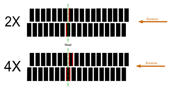
In 2× mode the P2Q handles only
the entering edge of the dashes (marked by red). In this case the base
resolution of the encoder (PPR) is doubled.
In 4× mode the P2Q processes each edge of the dashes. In this case the base
resolution of the encoder is quadruopled.
Recommended settings:
In case of 200-1000 PPR, 4×-mode,
above this range 2×-mode is preferred.
In a positionerror-free position the difference between the two signals is 0 (the dirrerence-counter stands at 0). The error signal comes from the difference of the two signals (counters) and their direction. This error signal can be read through the serial port (Serial). The error signal is the starting base for the complicated PID algorithm. The PID prepares the direction and PWM data for the bridge-controller.
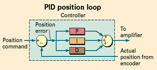
The adjustment of the more complex
drive-method (PID) is more complicated that that of the stepping motor
controller. During adjustment of the PID the tuning of the Controller to the
unit of the given motor + mechanics takes place (a little bit even to the
settings of the CNC control programme).
In case of these controllers the adjustment of the PID is supported by
additional electronics and by special software, we can provide a portable,
handheld, spectacular device. This can be purchased as an option. This device is
Profi2Q Servo Monitor, which stores and presents the transients of the servo
controller like a digital storage oscilloscope.
(Profi2Q Servo Monitor adapter, RS232C)
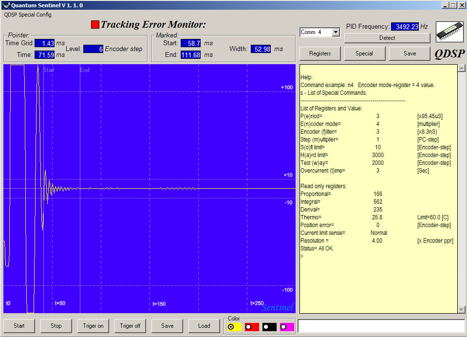
OR
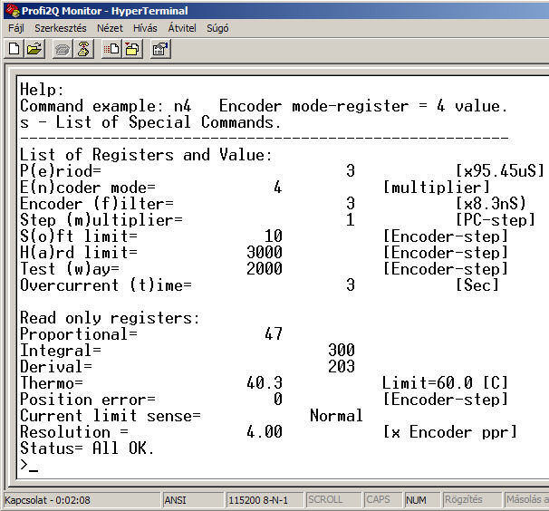
(Usage through Hyperterminal)
Applicable servo motors:
The motors intended to use must meet the following requirements:
must operate with a DC voltage lower than 90V,
must be a type with carbon brushes,
the nominal current consumption must lower than 26A,
the motor must be a servo-characteristic type (all the types equipped with an
encoder meet this requirement),
In case of types without encoder the following should be
checked:
Rotating their axis, it must rotate smoothly, without jerking. The types which
jump into the positions are not suitable.
Requirements of Encoders:
They must have 2 two-phase, so-called incremental-type channels (channel A and B).

(incremental channels with a phase-shift of 90 degrees)
Between the square-wave signals of the 2 or 4 channels (A+,
A-, B+, B- symmetrical or A, B assymetrical), - which are generated
continuously during rotation of the axis, - there is a phase-shift of 90
degrees. From the relation of the 2 signals the rotating direction can be
determined, from the number of pulses, the extent of the swing can be
determined.
Many encoder have besides that plus channels (e.g. index), these are not used
by the controller (they do not have to be connected).
If use only assymetrical encoder, then wired A+ and B+.
The electric signal levels of the channels must also be
matched to the inputs of the controller.
There are 2 types of the allowed signal levels:
1. TTL signal levels (with a signal level of +5V),
2. analogue, open collector trtansistor (OC*) outputs (the controller contains the internal 2k2 pull-up resistors and other signal forming parts).* OC= open collector (transistor output)

(encoder inputs)
The resolution of the servo motor will be determined jointly by the resolution of the encoder and DSP setting of the controller. This resolution can be further modified by other mechanical gearing of the CNC machine and the programmable resolution (which is the smallest programmable displacement) of the machine will be determined by all the above mentioned things.
The two-level protection system of P2Q:

(LEDs)
1. Independent protection systems. In case of their operation they make the motor stop by motorbrake and prohibit DSP. They give LED ("A" and "B") indication, as well as text messages in the „Status” register. Their operation can only be stopped by restarting DSP. Each independent protection system generates an error signal on the FAULT output. By this signal the CNC control-software running on the PC (e.g. Mach3) can also be stopped.
- Overrun protection of Hard limit (Error*) register
(its size can be adjusted):
If the error signal (Error*) exceeds the adjusted value, the DSP will stop the
motor by motorbrake and prohibits its further operation.
It performs first of all protection against reverse encoder connection and
seizure of the motor.
* Error register = error-level register, which measures the deviation between the required and actual mechanical positions in terms of Encoder steps. If there is no deviation, then its value is 0.
- Overload-protection of the motor:
If the current-limiting of the motor is continually operating and its operating
time exceeds the value of "Overcurrent time" register, then the protection stops
the motor and prohibits its further operation.
- Overload-protection of the controller:
The temperature of the heatsink is continually measured by a thermo sensor and
about at 60/80/100 °C it prohibits the further operation of DSP. It can be
adjusted by Service code.
- Stop input active (low level). If it operates, it willmake the DSP prohibit.
2. Protection through the PC. This cannot stop the Controller in itself, it generates only an error level on the FAULT output. If this output is connected to one of the inputs of the PC and the controlling software is properly configured then this signal is able to stop the operation without pulse-loss. In certain conditions the work can be continued witout producing wastes after fixing the error.
- Overrun of the Soft limit (Error*) register. It also produces a signal on the "A" LED as long as this state remains. This signal is first of all to check whether the trace tracking is geometrically true. It continually monitores the synchronism of the motor and the CNC software. When this becomes bad, it stops operation and gives a signal. The Fault indication can be prohibited by service code.
- Motor Peak-current limiting:
The DSP continually checks the status of motor current, and if its level is
high, the protection limits the PWM outputs. The fact of limiting is indicated
by lighting the "B" LED. This signal has no influence to the FAULT output.
LED signals and Fault output table:
|
Error |
LED_A |
LED_B |
FAULT |
Motorbrake |
Status register |
|
Current limit: |
- |
X |
- |
- |
- |
|
Soft limit: |
X |
- |
Programmable |
- |
- |
|
Hard limit: |
X |
X |
X |
X |
Message |
|
Motor Overload: |
X |
X |
X |
X |
Message |
|
Thermal protection: |
X |
X |
X |
X |
Message |
|
Stop: |
X |
X |
X |
X |
Message |
They stop P2Q and only RESET can clear this state.
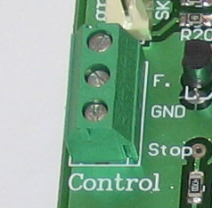
(Fault, Stop ports)
The Controller has an emergency-stop function, which can be
activated by a push-button located between Stop and GND pins. When this is
activated, the Controller stops the motor by emergency brake and prohibits its
further operation, as well as an error signal is produced on the Error output.
To resume this situation, the system must be restarted or press more 3s of "T"
button.
It is important to know, that emergency-stop always operates immediately in
any kind of conditions, while the Stop comand issued on the PC might as well
affect after several seconds because of the pulse buffer of the Controller.
The Controller got into oscillation because of wrong setting (PID) can only be
stopped by emergency-stop or by turning-off.
In full build-up, the protection must be wired in the following way:
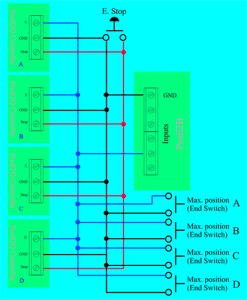
(integrated protection + end-position inputs)
The above figure showsw a 4-axis Serevo Controller, which occupies only 1 input on the Profi2B base card, yet both the Error signal and all the 4 pieces maximum end-position switch will be processed. When they work Mach3 will be stopped by E-stop (in case of suitable configuration). The circuit diagram contains the external E-stop push-button, which will stop Mach3 if it is properly configured (the signal of E-Stop appears on the Error output of the Controller). When the external E-Stop is operated, the stop without pulse-loss is not guaranteed (the determination of 0 point will be necessary posteriorly). The above presented figure does not show the end-position switches of the other end of the axes (or the Home switches), they also must be taken care of (see at Profi2B description)
Electric connections, wiring:

All the wires should shielded mounted.
The high-current wires (connection of motor and its power supply) and the inputs
of the encoder are on a screwed terminal. The cross-section of the wires is
maximum 1.5mm2. All the high-current wires should be shielded twisted
pairs. For this purpose the socalled industrial 4 - 20 mA signal cable, which is
a 4-wire (2 twisted pairs) shielded with a cross section of 0.5 mm2,
is very well suited (available in special electric shops).
The wiring of the Encoder must be done using shielded cables by
all means. Care must be taken of using the possible shortest wiring and placing
the wires far from high-current wires. The shielding must be connected to the
GND terminal located on the Encoder input terminal of the Controller. The
shileding (and the GND terminal) must not be connected to the metall case of the
CNC machine.
The metall case of the CNC machine must be connected to the protective ground of
the current outlet.
If power supply must be provided for the Encoder, the the power supply voltage
(if there isn't inside) must be filtered by a capacitor of at least 10 uF next
to the Encoder (the capacitor must be connected to Vcc and GND lines).
Care must be taken of the right connection of the motor power supply. In case of
wrong (reverse) connection, the Controller goes wrong.
The high-current witing must be placed as fas as possible from the Controller.
Connections:
Power Supply and Motor:
The motor power supply is connected to the Controller through SK1 terminal. Take care of the right polarity. Shilded wires must be applied

(Power Supply and Motor)
The outlet terminals of the DC motor must be connected to the SK2. Polarity does need to be taken care of, the rotating direction can be chaged within the CNC control programme. When selecton the cross section of the wiring, the nominal current of the motor must be taken into account. Shielded wires must be used.
Digital Power and Signal connection:
The digital power supply and signal connections are lines of pins. The pin-line connections are ed using standard internal PC (CD-ROM - motherboard), audio (shielded) cables. The usage of sush (shielded) cables, with wide black connector at both ends is strongly recommended. The connectors are positioned, reverse connection is not possible.
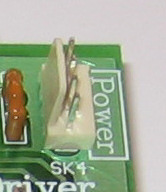
(digital power)
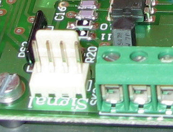
(Step/Dir signal)

(CD-ROM audio cabel)
Care must be taken not to exchange the signal and power line. Wrong connection may cause the Controller to go wrong immediately.
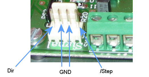
(Signal [TTL])

(digital power supply)
Exchanging the 2 wires may lead to damages.
The wires should not touch the heat sink (danger of melting).
Letter, A - D must be attached to the 4 pieces of Profi2Q Controllers, and the letter attached to the controller should be written onto it by an alcoholic makrker. Later, based upon this marking the bit allocation table - controller assgination can be performed.
Connection and testing of the Encoder:
The connection of the Encoder is realised through the SK7 + SK6 terminals. On the terminal the connections of Vcc and GND also can be found (if they were needed by the encoder).

(Encoder)
The encoder must be connected with shielded wiring by all means.
Care must be taken of the polarity of the encoder power supply, in case of revewrse connection it may go wrong.
Exchanging the channel A+ (A-) and B+ (B-) of the Encoder does
not cause any failure, but it leads to abnormal operation of the Controller. Whe
they are exchanged, the Controller will start the motor at maximum speed toward
one direction, because the feed-back will operate reversely.
Therefore the motzos must be connected to the
mechanical parts during the first tests.
If this might happen, the Controller would stop motor in 3s and would prohibit
its further operation.
Checking the connections:
Turn the all potentiometer trimmer of the completely wired Controller into approximately 1/3 position.
(potentiometer trimmers)Turn on P2B and the motor power supply.
gently move the motor-shaft by hand.If the motor suddenly starts (at a great speed), the the connection is reverse.
Turn off the Controller.If the motor dos not spin, then the connection is correct.
In case of reverse connection either the line A and B should be exchanged, or the excitation lines of the motor (SK2) should be exchanged.
Setup Registers:

(Sentinel)
Software setting-up:
The setting-up of the software is basically the same as that of written about Profi2B base card Detailed setting-up information can be found here , please read it carefully.
The following adjustment has a great importance:
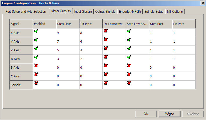
(Step/Dir and Step Low Active setup)
It is important that the Step Low Active signal should be set at P2Q Controller.
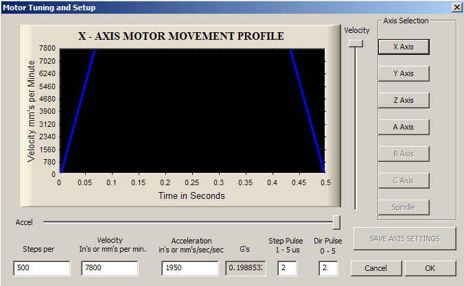
(Step Pulse and dir Pulse = 2 !)
Adjustment of PID regulation:
The full movement control of the motor is performed by the PID regulator, with the help of complicated mathematic procedures. The regulation works wth 3 parameters adjustable by the user. The 3 parameters are marked as P, I ,D parameters, a separate potentiometer trimmer belongs to each of them.
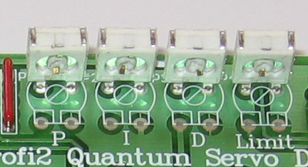
(P I D and Current Limit)
The amplification of these regulation parameters can be adjusted by these potentiometer trimmers.
