(MODBUS I/O Controller for Mach3)
![]() MBIO Peripherial
Controller
MBIO Peripherial
Controller![]()
(MODBUS I/O Controller for Mach3)
![]()
Modified: kedd, 2009. szeptember 01.

High level I/O handling...
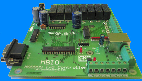
MBIO Controller is a standard peripherial card with MODBUS (Slave) communication. It provides output- and input extension first of all for Mach3. Its connection is carried out through an RS232C connector or by the means of a special converter through the USB port. With its help the service of controls and remote controls, which do not need extreme precise timing, can be substantially expanded. To perform such tasks it is not necessary to use the fast LPT, which does not have many ports. By its use control tasks like those in case of PLC can be performed. The ports of MBIO and port-bits and internal registers of Mach3 can be assigned by the means of a graphic editor. The peripherials will be handled based upon logical conditions determined by the editor. The setup and the way and logic of handling of a given peripherial can be saved and even a collection of peripherial handling routines can be established, which can be added to the system or can be removed from the system one by one. Such a collection can even be exported to other CNC machines as well. All this can be handled directly with Mach. This is a totally professional device, inpedendent from the motor control, this is an independent I/O controller.
Main technical specifications of MBIO:
- ability to receive 8 input switches/push-buttons (it can directly receive mechanical push-buttons).
- 8 relay outputs, with maximum load of 230V AC, 3A.
- 2 analogue inputs, receive voltage of 0-5V or potentiometers/thermistors of 1k-4k7.
- 1 MPG (receive of a 2-phase asymmetric encoder of incrementing type.
- 1 PWM output (5kHz, 0-11690 steps, open collector type output with maximum load of 30V, 200mA).
- 2 16-bit counters, with clear inputs.
- 1 UTP connector for remote control console.
- All of the I/O-s are equipped with LED indicators.
- Integrated switching power supply unit.
- RS232C serial connection (USB can also be used together with a converter).
- Firmware upgrade through ICP.
- Partially SMD-mounted PCB.

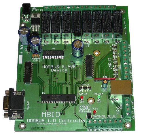


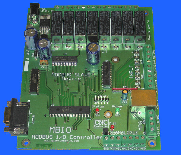
(click to zoom)
MBIO is first of all to control auxiliary devices (e.g. to PWM-control the revolution number of a spindle, to start the cooling pump, to operate loading devices, tool exchangers, etc.), and to remote control of CNCs. Because of the time-delay of the serial communication, their use is not recommended for reception of end-positions and HOME switches or for any other application where timing is cruical.
![]()
(Manual of MBIO, (Hungarian
language) pdf)
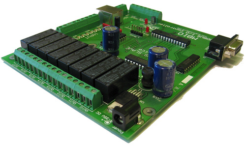
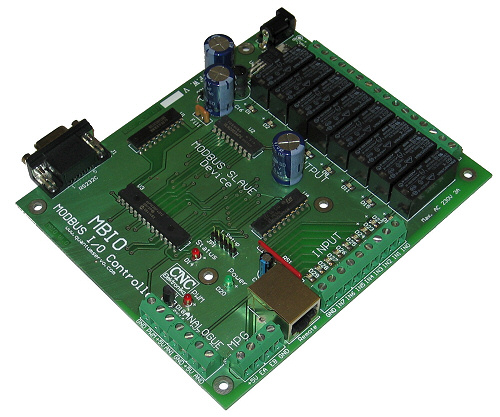
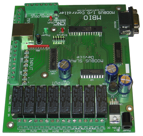
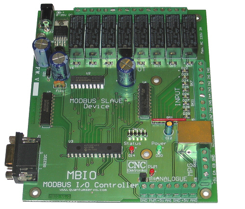
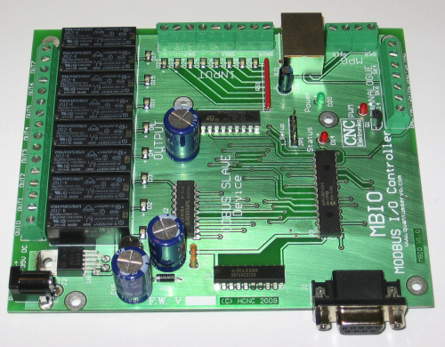
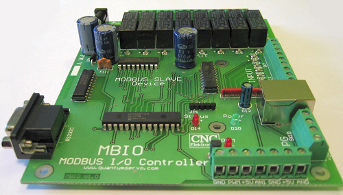
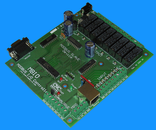
Build-up, lay-out and connections:
(MBIO)
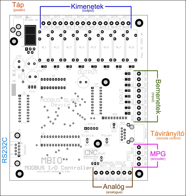
(connections)
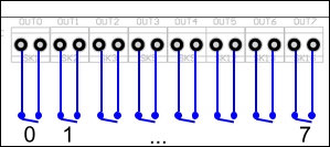
8 relay outputs:
Their terminal is marked with OUT0 - OUT7. The relays have 1 - 1 potential-independent make contact.
Their maximum load is AC 230V, 3A.
Each relay has its own LED indicator.
(digital, relay output)
All the outputs can be freely used.
8 digital inputs:
Their terminal is marked with IN0 - IN7. Each input has an internal pull-up resistor of 470 Ohm.
In standstill they are at high level (+5V),
in active state they switch to GND. Each of the inputs has a LED indicator.
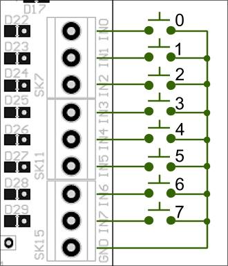
(digital inputs)
Transistors, push-buttons, switches can be directly connected to the inputs. The inputs marked with IN7, IN6, IN5 are parallely connected to the pins No 5-6-7 of the remote connector (UTP), ("or" relation).
1 MPG (Manual Pulse Generator) encoder
input:
Its terminal is SK8-SK10 in MPG field. On the terminal the incrementing 2-phase asymmetric TTL inputs marked with EA and EB can be found
beside the power supply connectors. They have an internal pull-up resistor of 3k3
and filtering circuit too.
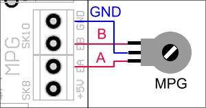
(MPG input)
EA and EB encoder ports are parallely connected with the pins No 2 - 3 of Remote connector ("or" relation). The suggested encoder resolution is 10 - 200 lines/revolution. The Controller processses the signals in doubling mode.
2 analogue inputs:
Their terminal is SK6; SK4 in the Analogue field. On the terminals the inputs marked with AN0 and AN1
can be found beside the power supply connector.
The signal inputs can receive DC voltage of 0-5V, or potentiometers, resistor networks of 1k -
4k7 (ratio switches), thermistors, etc.
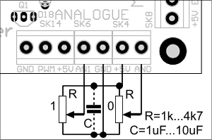
(analogue inputs)
In case of use of potentiometers building-in a "C" filtering capacitor connected near them is recommended. The A/D converter of the inputs is of 10-bit type (digit range: 0 - 1023). The wiring should be shielded. AN1 is parallely connected with the pin No 4 of the Remote (UTP) connector. They are in "or" relation.
1 PWM output:
Its terminal is SK14. On the terminal the PWM (Pulse Width Modulation) signal can be found
beside the power supply connector. The output has an open-collector transistor,
whose maximum load is 30V DC, 200mA. The transistor switches to the GND.
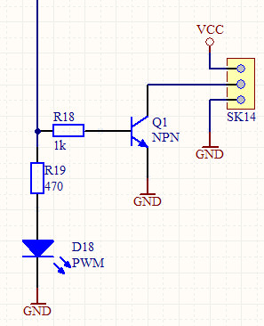
(Internal build-up of the PWM output)
Optocoupler isolation can be an option for signal reception:
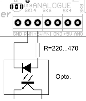
(Reception of PWM signal)
The frequency of the PWM output is 5kHz. Its control range: 0 - 11690.
2 Counters:
Their terminal are the points marked with IN0 and IN1 of the Input field. Counter0 is connected to IN0 and
Counter1 is connected to IN1. The counters will step for falling edge. Their resolution is of 16-bit,
(with value range of 0 - 65535).
(At the same time IN0 and IN1 are also the iputs of the counters)
The counters can be cleared by software (through the MODBUS). The states of the clearing bits: 0=Reset, 1=Counting.
Power supply connector:
The Power Supply connector is a connector of 2.1mm type. Its internal pin is the positive pole (+).
The power supply voltage is unstabilised 12V DC, with a maximum current load of 300mA.
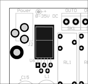
(power supply connector)
Attention!
As opposed to the note on the PCB, the power supply voltage must be ONLY12V DC. It does not need to be stabilised.
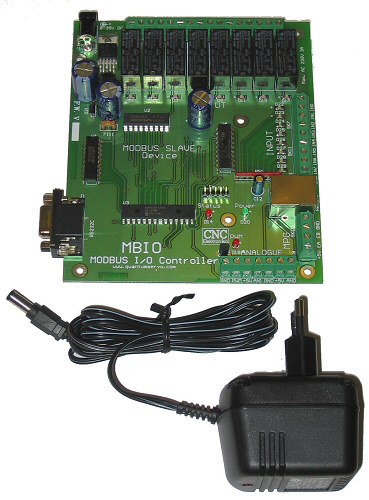
A plug-in AC/DC adaptor of 230 AC/12 DC can be provided for the MBIO Controller, in case it is needed.
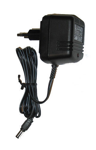
(Power supply of 230 AC/12V DC)
RS232C serial port:
Its connector is a type of SUB D9 "female", with standard serial port lay-out.
The suitable cable is a standard RS232C extension cable, which has a SUB D9 "male"connector on the PC side,
and has s SUB D9 "female" on the MBIO side without cable exchange. In case of using USB,
an RS232C-USB converter is necessary.
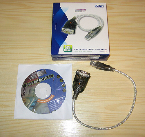
(converter RS232C - USB)
Further details on the adaptor can be read here.
Signal indicators:
Status LED : indicates the active communication (successful addressing and perfect data-transmission),
Power : indicates the presence of +5V,
PWM : indicates the presence of PWM signal and its duty level.
All the inputs and all the outputs have LED indicators. These show the active states.
The base configuration of MBIO MODBUS:
MBIO uses standard serial MODBUS V1.0 Slave protocoll, so it can be used together with all software using this protocoll. (among others with Mach3 too).
Serial communication: 115200 bit/s, 8-1-N
The Slave address of MBIO: 1
The MODBUS communication can reach the inputs and outputs based upon their addresses and type. The following table shows the full address range grouped by types.
| Address allocations of the registers of MBIO (DSP V1.0): | |||
| Registers type: | Címe: | Function (sharing): | Legend: |
|
Discrete Inputs Base address: 0000. |
0 | IN0/Counter0 | Inputs |
| 1 | IN1/Counter1 | ||
| 2 | IN2 | ||
| 3 | IN3 | ||
| 4 | IN4 | ||
| 5 | IN5 (Remote7) | ||
| 6 | IN6 (Remote6) | ||
| 7 | IN7 (Remote5) | ||
| 8 | empty | Spare signalling bits | |
| 9 | empty | ||
| 10 | empty | ||
| 11 | empty | ||
| 12 | empty | ||
| 13 | empty | ||
| 14 | empty | ||
| 15 | empty | ||
| Input
Registers Base address: 1000. |
0 | MPG (Remote MPG 2,3) | Roll-over Encoder register (type of 16-bit) |
| 1 | AN0 |
Analogue/Digital converters (type of 10-bit) |
|
| 2 | AN1 (Remote 4) | ||
| 3 | Counter0 | 16-bit edge controlled counters |
|
| 4 | Counter1 | ||
|
Output Coils Base address: 2000.
|
0 | OUT0 | Relays |
| 1 | OUT1 | ||
| 2 | OUT2 | ||
| 3 | OUT3 | ||
| 4 | OUT4 | ||
| 5 | OUT5 | ||
| 6 | OUT6 | ||
| 7 | OUT7 | ||
| 8 | Counter0 RESET | Counter0 control 0=Reset | |
| 9 | Counter1 RESET | Counter1 control 0=Reset | |
| 10 | empty | Spare control | |
| 11 | empty | ||
| 12 | empty | ||
| 13 | empty | ||
| 14 | empty | ||
| 15 | empty | ||
| Output
Holding Registers Base address: 3000. |
0 | PWM | PWM,
range: 0 - 11690 (5 kHz) |
| 1 | empty | spare | |
(Registers of MBIO)
The registers without function are addresses for later development.
Types of Registers:
Discrete Inputs : input registers, each bit is available (each bit can be separately addressed, querried).
Input Registers : 16-bit input registers (integer registers without sign),
Output Coils : outputs that can be controlled by bits (each bit can be separately adjusted).
Output Holding Registers : 16-bit, output registers (integer registers without sign).
(MODBUS Peripherial Controller)
Mach3 MODBUS set-up for MBIO Controller:
This description is a reference for MODBUS communication of Mach.
Mach3 CNC Controll programme supports MODBUS type of I/O controllers.
Mach3 presents itself as Master controller, to which Slave (auxiliary) controllers
can be connected. It communiates with the Slave controlers based upon their addresses.
The MBIO Controller is a Slave device itself, whose address is 1.
The slave devices contain the physical inputs and outputs as well as other peripherial devices
(PWM, A/D coverters, encoders, counters, etc.). The querries are alawys initiated by the Master device,
The frequency of the pheripherial handling can be adjusted here too.
Mach3 (who is the Master) must know the place, speed, the dataformat of the serial communication,
the slave address and the type, the addresses and the amount of the registers of the slave device.
After setting-up these, the assignment of the registers/bits and the inputs, outputs and internal registers of Mach3
and setting-up their functions follows. The assignment is supported by PLC-type internal auxiliary programmes.
It is extremely flexible.
Later further information can be found on this flexibility.

To establish the base communication the followings steps must be performed:

(switching on the MODBUS handling)
This is the most cruical step. Switching on the MODBUS handling.

(Important addition)
It is important even the relay is controlled not from the LPT port. It is necessary for the correct operation of the screen button.
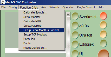
(Configuration of MODBUS)
This is the place to reach the most important MODBUS panel
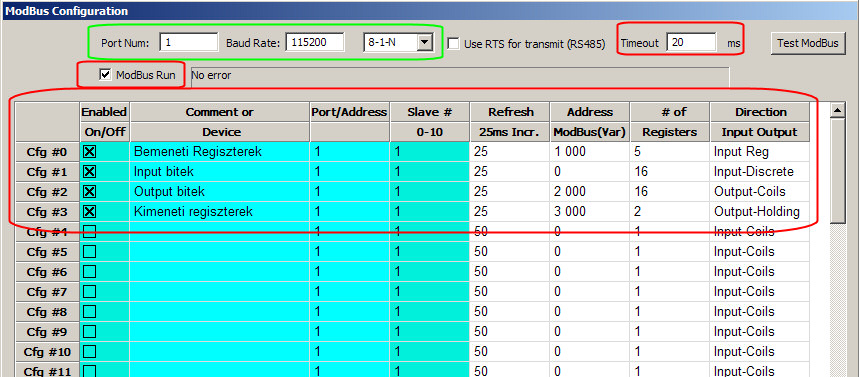
(Main control panel)
It is the source of all the MODBUS set-up. The register types written in the above table, their addresses, their amount must be here adjusted, so that they could be integrated by Mach into its own system. The Slave device registers can be addressed and reached based upon these values. The address, speed and parameters of the serial port must be adjusted here too. (Partially) everything must be adjusted according to the above picture.
The only thing that can change is Port Num= the port-number of the serial port of the connected MBIO (or in case of USB converter the port-number of the virtual port)! All the other must not be changed.
The value of the communication Timeout is 20 ms or more.
The whole will be switched on by ModBus Run.
The registers of MBIO are defined by the Cfg #X lines. The caption to the columns:
Enable = the line will be enabled,
Comment = apparaisment of the line,
Port/Address = ? (By changing it I experienced no effect...),
Slave# = the address of the Slave device (in case of MBIO it is 1),
Refresh = the frequency of the querry in ms (the lowest value is 25ms),
Address = the internal address of this type register of the device (in case of MBIO it is according to the figure),
# of Registers = number of registers (see the figure in case of MBIO!),
Direction = register type (See the figure in case of MBIO!).
If all these are properly adjusted, then the Status LED of the MBIO begins to blink at a speed according to the adjusted Refresh value. It is worth proceeding from line to line and testing whether the adjusted values are suitable (it is indicated by the Status LED).
After all these all the MBIO registers, relays, inputs, etc. can be reached using the Brain Editor of Mach3.
Further descriptions discuss the sample configurations of MBIO. Mach provides possibility to assign peripherials to its internal operation at high level, therefore the number of the possible variations of the adjustments is very high. Here there is no possibility to discuss all the variations, therefore only some samples from the many possibilities are offered.

Proceeding further: To show how to use Brain Editor and Brain Control, an example of establishing an input - EStop relation can be found here.
![]()