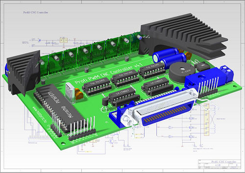
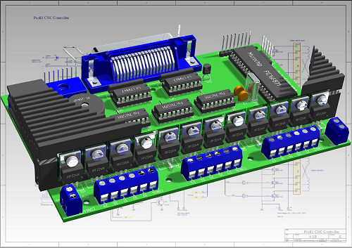
Profi1 CNC Controller
The following written things naturally apply to both 3D, and 2D controllers!
![]() Service
Service![]()
Profi1 CNC
Controller
The following written things naturally apply to both
3D, and 2D controllers!
Modify: 2006. 10. 14.
Check of the driver stage (FETs):

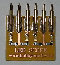
(SMD LED Scope)
The FETs of the driver stage can be checked clearly visibly, fast and exactly by the mean of the LED Scope. With the help of 4 LEDs and 4 resistors the excitation states (T1, T2+T3) can be made visiblel.

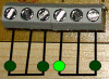
(The signals of
the LED Scope in case of sound FETs)
Watching the intensity of the LEDs the full (T1) and
partial (T2+T3 PWM) excitation states can be seen.
Its circuit diagram is in:
Ledscope.pdf (13 kB, pdf).
The ready made circuit must be connected instead of the motors and the
controller must be driven at slow speed (1 step/second) by using a CNC control
software (such as Mach2,
Hobby CNC PWM Manager, etc.).
In case of sound FETs it must work according to the above animation (the
direction does not count) (full intensity means T1, reduced intensity means the
T2+T3 PWM states).
If any states differing from these can also be noticed (eg. sustained faulty LED
with full intensity, one or more dark states, that means break of an FET, a
resistor, a line on the board, or perhaps PIC fault).
 LED
continuously lighting = sticked phase. The FET belonging to that must be
replaced.
LED
continuously lighting = sticked phase. The FET belonging to that must be
replaced.
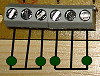 One
or more dark states = FET controlling error. The state of the FET and
controlling resistor belonging to the FET, or perhaps the the printed board must
be checked.
It is possible to
check the FETs in
PC-Link mode too.
One
or more dark states = FET controlling error. The state of the FET and
controlling resistor belonging to the FET, or perhaps the the printed board must
be checked.
It is possible to
check the FETs in
PC-Link mode too.
![]()
In
PC-Link mode the particular FET can be directly switched on or off, which
also can be checked visually by the means of LEDs.
A fast test to test the states of FETs:
If you enter the controller into PC-Link mode, it will turn off the PWM excitation and will stop all the FETs.. If you try to move it in this state, th motors will turn as if they were switched off (i. e. easily).If it is not so, (you need force to move it), then some of the FETs belonging to that motor is broken down. Then it is time for the LED Scope.
Uneven run of the motors:
At low speed the motors perform a reciprocating motion, at highr speed they run normally. What may be wrong?
·
The position holding force is low. The brake torque (T2+T3) should
be increased up to at least 50% (by using Hobby
CNC PWM Manager). The most simple way to do it is to increase T3 so that the
duty cycle should be about 50 %.
Or if the motors
are operated at elevated voltage (Upower >Umotor), the value of T1 should be
decreased. If the core of the motors becomes saturated (it can be observed
especially at low speed), the flux lines spread out from the core of poles and
this can cause a distortion in the neighbouring poles. In this case the motor
may become liable to a jerky run. The smooth run must be adjusted by gradually
decreasing of T1. The smooth motor control with programmable acceleration of
Mach2 is excellent for performing tests.
More detailed information can be seen in the description of
Motor tuning.

(Run
of a correctly adjusted motor. (wmv video, 594 kB))
Standing Motors with screaming during the first start:
During the first start of
untested controllers (e.g. in case of a kit) it may happen that the one of the
motors, - which belong to the X axis, - is sreaming and standing though the
phases are correctly connected (e.g. they were searched by the direct contacting
method). The end positions have not been determined yet. The controller is just
about to determine the end position data, but the value of TF is too low for the
particular system (motor + mechanical parts) and the motor cannot start. As it
is known, the controller determines the end position data at the value of TF
(and at the same time it is the start value of the overdrive signalling too).
In this case you have to press the end positions XV1, YV1 and ZV1 one after the
other (i.e. instead of the motor you give the directions by hand, it does not
matter if these are not the correct ones yet)! Then take the controller into PC
Link mode and increase the value of TF (the basic setting
can be downloaded from here). After then you have to make the controller
determine the correct directions again (push button +Power ON).
Error LED
(signalling of
pulse interference)
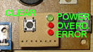
Meaning of the E LED signalling:
Pulses with distorted signal form, or too fast Step pulses (max. processing speed: 13000 Step/sec simultaneously on the 3 axes). These cases can be observed particularly when blur needle pulses arise on the Step line or on the ditital power supply lines. The PIC is not able to process the Step signal.
It can occur at Kcam4 and other software timers (Because
the multi-thread processing of Windows the signal form of the software timers is
sometimes distorted or fractured), these errors (which are caused by the
controlling software) are handled by the Firmware of the PIC, (by the means of
internal digital 3 point-filters) so they cannot cause any errors in the
product. In Mach2, - because of its hardware timers, - such errors (and error
signal) cannot be observed!
Could such an error signal be observed during the application of Mach2, it can
be caused by the followings:
- There is an interference source near the controller. This can be a sparking motor (e.g. motor of a mill, exhaust ventilating system, etc.), welding machine, cell phone, etc. In this case the source of interference must be searched and must be eliminated. The interference can spread on radio frequency (e.g. . sparking, cell phone), or through the 230V network, getting through the filtering of the power supply.
- Too long or of poor quality LPT (printer) cable. Recommended maximum length: 3ms. Solution: shortening/replacing/shielding the cable.
- Presence of interfering softwares on the controlling PC. Solution: Using of clean Windows independently running Mach2 after installing XP (elimination of the inerfering programme, such as antivirus scanners, drivers, etc.).
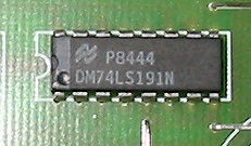
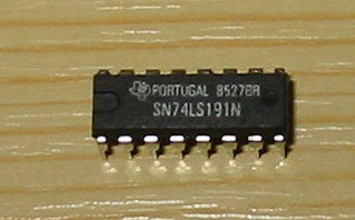
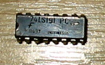
![]() 74LS191
74LS191![]()
(For those who by the parts themselves!)
Not all made of this counter IC (74LS191) suits perfectly. The different manufacturers use different technologies with different internal arrangaments for this IC, therefore substantial differences have been experienced regarding the noise immunity (excitability). Because of the great number of the controllers manufactured and testes, there is sufficient experience which make of this IC should be avoided and which of them have proved.
| Good and usable types: | Bad and NOT useble types: |
|
|
|
|
|
|
Strongly recommended!!!
![]() End position inputs
End position inputs![]()
(Mistakes made by novices)
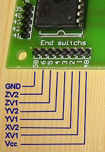
Among the mistakes made by novices breaking through the PIC from outside from the end position inputs stands at the first place. If voltage from outside may get to the inputs (e. g. + voltage of the motor) even for a moment, the PIC goes wrong at once! It may happen usually during „wire” experimentation, or because of a wiring error. The inputs need careful attention! The faulty can produce a wide variety of symtomps. There were cases when it was willing to turn the motor only for one direction (because of the faulted end position it supposes that one of the end positions is depressed), there were cases when the PIC was slightly warm (normally the PIC never gets warm!), and after some minutes it went crazy, but there were also cases when the PIC was tottally dead..
If you susoect such an error, you can make sure about that by doing some
measurements. With the controller switched off you have to measure the
resistance between each of the end point inputs (XV1 ... ZV2) and the ground
(GND) by an Ohm meter.
In case of a good input the resistance must be 7~10 MOhm or 20~26 MOhm depending
on the polarity of the mesuring instrument between an end point input and the
GND.
In case of faulted input, the resistance is about 0~500 Ohm.
As for the PIC with faulted inputs, there is no other choice than to replace it!