(Possibilities to extend the system)
![]() H1 Expander
H1 Expander![]()
(Possibilities to extend the system)

Modified: 09.01.2009
Discontinued!

|
Content: |
H1 CNC Controller in basic configuration is capable to control three 3 independent axes through 1 LPT (printer) port.
![]() H1
Promo videó (wmv, 4.66MB)
H1
Promo videó (wmv, 4.66MB)
Applying two LPT ports and two H1 CNC Controllers the system is capable to control 6 independent axes (motors) (recommended CNC controller software is Mach3).
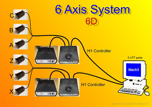
(6 Axis system via two LPT)
When applying 2 LPT ports the bit allocation of each Controller is the same as of the basic bit allocation, only the the base addresses of the ports are different.
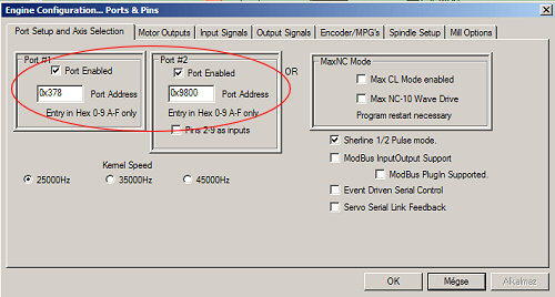
(The LPT base address identifical of the ports)
|
Function: |
Place/Job: |
Pin number of LPT: |
|
Motors |
A Step |
4 |
|
A Dir |
5 |
|
|
B Step |
2 |
|
|
B Dir |
3 |
|
|
C Step |
6 |
|
|
C Dir |
7 |
|
|
Outputs |
MILL Relay |
14 |
|
Inputs |
P7 1. |
15 |
|
P7 2. |
13 |
|
|
P7 3. |
12 |
|
|
P7 4. |
11 |
|
|
P7 5. |
10 |
|
|
P7 6. (common GND) |
- |
(H1 Base bits)
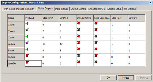
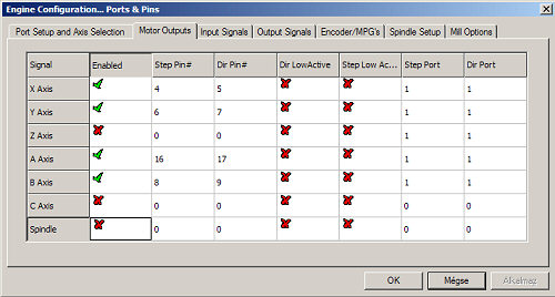
The next configuration example shows the adjustments of a six-axis machine:
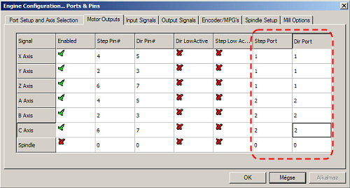
(6D system motor sitede config)
The individual H1 Controllers are indentified by the port numbers of Step Port and Dir Port. In the example the X axis is controlled through axis „A” of controller No 1, Y axis is controlled through axis „B” of controller No 1, Z axis is controlled through axis „C” of controller No1, „A” axis of the CNC machine is controlled through axis „A” of controller No 2, „B” axis of the machine is controlled through axis „B” of controller No2, and „C” axis of the machine is controlled through axis „C” of controlled No 2.
In a system with 2 LPT ports all the outputs and inputs of the controllers are available (2 pins for each output, 10 pins for each input), which can be differentiated based upon the # number of the Port.
A further possibility is the fact that 2-2-2 axes of the controller can be handled as 1-1-1 logical axis (e.g. X) through the slave mode of Mach3.

(Axis logic slave mode)
The example shown in the figure: the X axis of the CNC machine is done by 2
motors at once: by the axis „A” of the H1 controller connected to port No 1, and
by the axis „A” of the controlleraz connected to port No 2. The Y axis is also
done by these 2 motors: by the axis „B” of the controller No 1 and by the axis
„B” of the controller No 2. In the end Z axis is done by only the axis „C” of
the controller No1, and there is still a separate axis, an axis „C” of our CNC
machine, which is done by the axis „C” of the controller No 2.
This drive mode is the synchronous drive (each logically assigned motor rotates
at once). It is used first of all to assign motors to one side of foam cutting
machines, but it can be equally well used when driving an axis by two smaller
motors instead of one bigger one.
The expander makes possible to configure different axis numbers and drive
methodes using only 1 LPT port. The expander rearranges and allocates the
possible outputs and inputs of our only LPT port. Standard printer cables can be
applied.
By the use of the Expander the criterion, that only one motor should be
connected to the outputs of the Controller, can be fulfilled, and inspite of
that, driving one or more axes by 2 motors can also be realized.
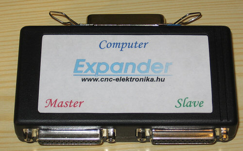
It has one input, which must be connected to the LPT port of a PC.
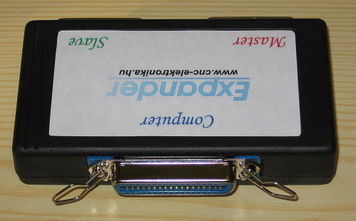
It has 2 outputs:
Master: this output carries the control signals without bit-transformation. The bit-allocation of H1 Controller connected to that is the same as the original bit-allocation, and all of its outputs and inputs can be used (1 relay and 5 inputs).
Slave: this output carries the control signals after bit-transformation. The bit-allocation of the H1 Controller connected to that differs from the original allocation and only its output can be used (1 relay).
Important: The motor”B” of the Master H1 controller is in forced sync with the motor „B” of the Slave H1 Controller. The other motors are physically independent, but they can be logically assigned at any time!
|
Function: |
Place/Job: |
Configuration pin number (LPT) : |
|
Motors of the master |
A Step |
4 |
|
A Dir |
5 |
|
|
B Step |
2 (forced sync) |
|
|
B Dir |
3 (forced sync) |
|
|
C Step |
6 |
|
|
C Dir |
7 |
|
|
Motors of the slave |
A Step |
16 |
|
A Dir |
17 |
|
|
B Step |
2 (forced sync) |
|
|
B Dir |
3 (forced sync) |
|
|
C Step |
8 |
|
|
C Dir |
9 |
|
|
Relay of the master |
Mill Relay |
14 |
|
Relay of the slave |
Mill Relay |
1 |
|
Inputs of the master |
P7 1. |
15 |
|
P7 2. |
13 |
|
|
P7 3. |
12 |
|
|
P7 4. |
11 |
|
|
P7 5. |
10 |
|
|
P7 6. (common GND) |
- |
(2 pcs. H1 Controllers via Expander, Setup)
Examples for system configuration
(some possibilities)
5D

(5D system, with 1 syncron motion)
(Example for 5D system setup)
In this example this 5D CNC has the following axes:
X, Y (driven by two motors), Z, A, B
The actual axis-assignments can be freely choosen by rearranging the bit allocation. There is only one important thing: the axes „B” of the two controllers are forced to be in sync and the inputs of the slave controller are not available.
4D
(2D+2D foam cutters and 4D mills)
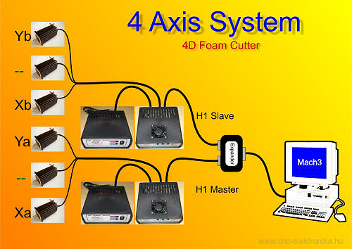
(Typical system config for 4D Foam Cutter)
Typical configuration if that of the 4D (2D+2D) foam cutters (suitable for cutting cones too). Xa and Ya are for the motors moving the frame of one side, Xb and Yb are the motors moving the frame of the other side.
(4D configuration
of foam cutters)
The frames moving the cutting fibre on the two sides can as well be moved
independently from each other by proper programming of axes X-Y and A-B (cutting
cones).
Here the axes „B” being in forced synchrone are not used (they can be built in
as a rotatory axis).
2D
(a typical configuration of a 2D foam cutter)
(4 Motors, 2D Foam Cutter with syncron motion)
2D foam cutter, moving maximum 4 motors (2 on the axis X, 2 on the axis Y, in sync).
(Bit config for 4 motors via 2D system)

(Logic config for syncron motion)
One side X=Master A, Y=Master B
The other side X=Slave A, Y=Slave B
It is suitable for cutting paralell edges.
The axes not configured here (axes „B”) can be freely used (e.g. as a rotatory axis).
As a special driving, the synchronous driving of three motors can be solved as well (binding of the B-B motors being in forced sync and one logical axis).