 Programming,
Cycles
There are various names for cycles: subroutines, patterns, loops and
macros.
Cycles are very useful for machined features which are repeated, they
only have to be programmed once so saving time, space and reducing the
possibility of error.
In the main they fall into three categories
-
Fixed or Canned Cycles, supplied by the control writer or machine tool
builder. They can not be changed by the machine user and are available
to all programs. Drilling cycles are an example of these.
-
User Cycles, written by the user. They are available to all programs and
are loaded and saved in the main program memory of the machine. A standard
feature specific to your business may be programmed and made a User Cycle.
An example may be if a keyhole shaped slot is machined in a lot of your
parts it may be made a User Cycle.
-
Program Cycle or subroutine, written by the user. They are attached to
a specific program and loaded or saved as a part of the file. An example
would be a specific shape machined more than once in a particular product.
Some or all of the above may be available on your machine. Additionally
the method of using them changes from machine to machine.
Here are some examples of the Bosch CC100 controllers cycles. A control
which supports all the above methods.
Fixed cycle, drilling.
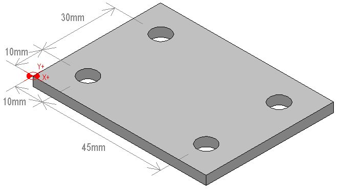
The following component is to be drilled.

The Bosch controller uses G81 to activate the drilling cycle and G80
to cancel a cycle. The parameters V1 and V2 are used for clearance height
and drilled depth respectively.
The component is 5mm thick plastic, the spindle speed has already been
set and a feedrate of 1500mm/min will be used.
The control generates the following sequence of moves for each position
following the G81 command
Move in rapid to the X and Y position.
Move in rapid to the clearance height.
Move in feedrate to the drilled depth.
Move in rapid to the clearance height.
The program section would be
N300 G81 V1=5 V2=-7
N310 F1500
N320 X10 Y10
N330 Y40
N340 X55
N350 Y10
N360 G80
User cycle, machine a circular hole.
In the Bosch controller the user cycles are loaded into memory in the
same way as programs and given a two digit number.
To call the user cycle the command G8xx is used where xx is the cycle
number. Parameters may be used to change the dimensions of the cycle feature.
A simple cycle to machine a round hole may look like this.
N100 (CIRCLE CYCLE)
N110 (V1=DEPTH OF CUT)
N120 (V2=RADIUS)
N130 (V3=FEEDRATE)
N130 V8=-1 V4=-2
N140 V5=V1*V8
N150 V6=V2*V4
N160 V7=V2*V8
N160 G91
N170 G1
N180 G42
N190 X=V2 Z=V5 F=V3
N200 G2 X=V7 Y=V2 R=V2
N210 Y=V6
N220 G1
N230 G40
N240 Y=V2 Z=V1
N250 G90
N260 M2
The use of parameters allows any radius circle to be machined, the Bosch
controller uses M2 as an end of cycle command.
To use this cycle assuming that it has been given the number 24, position
the machine where the hole is to be machined and call the cycle,
N420 G0 X-34 Y61.4
N430 G824 V1=15 V2=17.3 V3=1200
N440 G0 X34
N450 G824
Program cycle, specific shape.
The Bosch controller uses G22 Px to call a sub program, the sub program
is put at the end of the main program after the M30 and given a number
x.
N10 (PROGRAM START)
.
.
.
N230 G0 X-24.1 Y97.4 Z10
N240 G22 P20
N250 X-14.1 Y67.4
N250 G22 P20
.
.
.
N420 M30
N430 $20
N440 (MACHINE L SHAPE)
N450 G91
N460 G1 F1000 M8
N470 G42 X10 Y-10 Z-12
N480 Y-20
N490 X-20
N500 Y10
N510 X-10
N520 Y30
N530 X30
N540 Y-30
N550 G40 X-10 Y-10 Z12
N560 G0 M9
N570 G90
N580 G99
The $20 is a label and G99 is the return command.
Back to programming page

 Programming,
Cycles