(basic error detection and reparation)
![]() H1
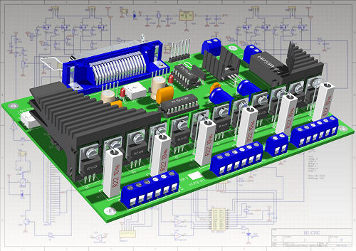
CNC Controller Service
H1
CNC Controller Service![]()
(basic
error detection and reparation)

Last modified: 11.16.2006
Only expert electronician with adequate equipment may attempt to repair primitive reparations too! Both the reparation and the try at reparation at home can cause the loss of guarantee by the finish-assembled and tested Controller! Only in the event of unwarranted or other constructed Controller will be expedient the reparation at home. You may do it too if the transport costs are more than the cancel-part price.
FET end stage (drive line) checking, reparation:
The stepping-motors are driven by 4 peaces of FET - per axes. The 2-2 FETs (by the same motors)are switched to the M- (motor minus) across shunt resistance.
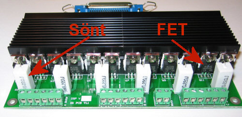
(FET drive line, Sönt=current sense, FET=FET)
Every FET are mounted isolated to 2 peaces of heatsinc.
In case you have surmise that something is wrong in your FET soundness (incandesced, seized-up motor, unequal running,…) you may assign with this test the operability of your FET:
With the Config Jumpers interdict the motor of the questionable axis and restart the Controller:
Strength of restfulness energizing:
Jumper 1:
Jumper 2:
Small (base adjustment, recommended)
-
-
Average
2-3
-
Full energizing (silent operation)
-
4-5
Power-of motor
2-3
4-5
(Position of Config jumper)
With switched-on Controller and with the Jumper position “Power-of Motor” perform the test! Rotate the axis of the Motor with your hand. You can turn the axis in case of faultless FET as by the switched-off Controller (relatively easily).
If the motor turns heavily or warms than one or more FET from the adherent 4 peaces are faulted!
If the FET is faulted, the Controller can’t switch off the energizing of the motor, so you have to turn off the supply voltage of the motor (or the whole supply) as soon as possible. Power so high voltage to the motor supply voltage input witch can not damage the motor neither under continuous energizing! This voltage is the Motor reference voltage (what is signed on the Motor) or lower.
With switched-on Controller and reduced motor supply voltage disconnect one by one the motor endpoints on the wrong axis (onlythe phase endpoints and not the coil-center)! After every disconnection probe to rotate the axis, if it is hard to move than that phase was correct!
In the event you can turn the axis easily, then the FET of that endpoint was faulted! Follow the wiring by serial terminal on the PCB and exchange the adherent wrong FET!
By the FET exchange you have to use only the same type as the other (correct) FET! Different types can cause asymmetrical agitation (running)! By the insulating of the FET take additional care because the wrong coating may cause elaborate errors!
It is expedient to check with a testing instrument the exchanged FET’s coating too. For measuring you have to disconnect the shared shunt resistance and all of the motor endpoints on the wrong axes. After it you have to measure the resistance between the FET flag and the fixing screw of the heatsinc (the correct value is infinite). If the value is not correct, you have to look over the wholeness of the mica and the plastic insulating ring!
Attention: without disconnection of the shared shunt resistance and connected motor ends you measure not correct value (fault)!
Attention! Be careful with the free wire-ends under voltage, because it may cause serious mistake in the Controller contacting to the wrong place!
Interference eliminator:
The H1 Controller have stronger interference eliminator as the Profi 1 Controller. If the digital supply voltage and the motor supply voltage are operating from different transformer only in that case can be operate acceptably this interface elimination! The noise generated by the motor can’t get into the digital side!
If the supply filtering is deficient (required min. 1000uF) or near to a forceful noise source (e.g. sparking mill-motor, arc welder, light tube,…) can be occur impulse noise (plus or loss by the stepping)!
In this case you have to check the electrical noise sources in the ambiance:
- commutator sparking by the mill-motor,
- arc welder under operation in the near,
- dust extractor sparking,
- etc.
As far as possible you have to remove the noise source (brush exchange, installing an anti-noise into the 230V supply wire, operate from an other appliance plug, etc.)! It is rewarding to assemble the digital feed wire screened (you have to connect this screening to the GND, can’t flow any current on it)!
In case of big fault you can observe pulse-bug by the LED’s of the axis:

(normal pacemaker)
The sequence of the LED flashing may change (it it disinteresting because the inaccuracy of the resonators), the speed depends from the Config adjustments! The irregularity in one axes shows the deficient interface elimination!